


Well, where to start. Obviously the whole process of building your own car comes with a whole load of decisions to be made, after which engine we wanted to use, the most important things for this project are suspension and brakes. That’s a personal viewpoint of course, but if the suspension and brakes on a vehicle aren’t right then everything else will suffer, not to mention being dangerous!
I’m going to try and take you through what was 24 months worth of thinking, trying, failing, trying again and failing again in this short section, but it’s really not worth going into every little detail, but feel free to post a comment if you want something specific answered.
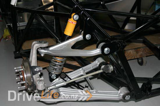
As mentioned earlier on in this series, we have decided on using donor suspension arms and brakes from a Corvette C5. These are a very popular solution for a lot of scratch car builders as the suspension pickup points are reasonably straight forward, they’re light weight, easily available and the cost is more than reasonable.
Unfortunately for some reason, even up until very recently, GM thought it was the best idea to use leaf springs in the rear of the Corvette. That means that they only needed to allow for room for a shock absorber, not a spring. That combined with the length of the V12 engine this means that the gearbox is slightly back from where a V8 would allow us to be, further creating space issues with where the rear shock absorbers used to fit.
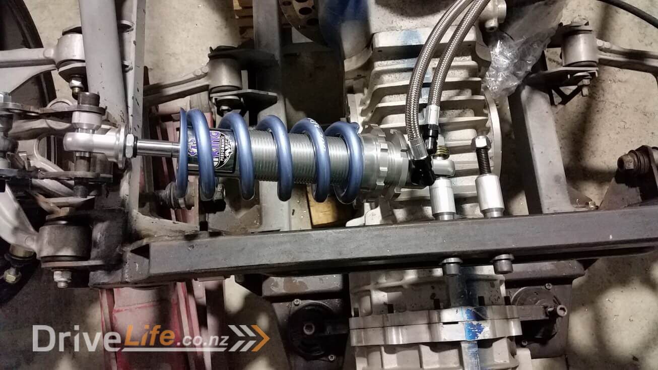
We wanted to make the FZ12 “current” where we could and really shift away from a “cheap” or “easy” track if it wasn’t going to be what we really wanted. Suspension was one of those areas and I was lucky to find Viking suspension from the USA. These guys were another example of suppliers that I’ve already found in other areas, where they had a product that they were looking to bring to the market and were keen to help. We had to wait for the prototype parts to be made etc, but the timelines worked out for us. Their system is very unique, but we’ll write a separate entry for this later to go into more detail. For this episode though, the size of the actual coil over strut is no larger than you’d expect to find from any supplier, but since the spring is combined with the shock absorber there’s simply no room in what would be a traditional position.
This is something that actually became obvious quite quickly. We tried mocking up a small spring to see if we could realistically get clearance, but it wasn’t to be. It only just had space in the best position but when it moved up or down it caused issues.


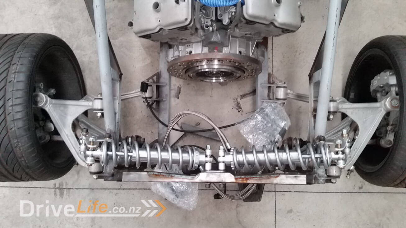
So now to figure out what other people did in this situation and see if it makes sense and will work for us. After many questions, Googling and general head scratching I settled on what is sometimes referred to as a “rocker” or “pushrod” system. There are 2 main advantages, the large shock absorber is replaced with a much smaller pushrod, which solves the space issue. The second benefit is that the shock absorber moves inboard of the suspension so moves the weight closer to the centre of the car which is beneficial.
Other people had used what I felt was a very compromised setup with some average looking brackets that attached to the front of the lower arm and then they put a normal coil-over on the front of the arm. Technically it obviously works, however it’s far from what I would call a well engineered solution and also didn’t really fit with the “supercar” theme that I think the FZ12 deserves.
So now that I had decided that we needed to design some kind of pushrod system I had to take what very limited skills I had and try to see what I could come up with. When this project got started I purchased a simple 3D printer to be able to make test parts or simple molds etc and so I was able to use this to make up some basic rocker arms. These obviously will not take any real load, but they’re purely to get dimensions and prove a concept instead of cuttings steel constantly. Then I needed to find a way to convert the pushrod force into something that I could attach to the shock absorber. I used some basic roll cage tube to make a mount and found a local supplier (John from Suspension Developments) that was able to supply some bearings for the rocker arm to rotate on. The same supplier was also able to help with some basic pushrods and spherical bearings.


All of the design shown above seems to be really simple and you would think that it shouldn’t / wouldn’t take long to do, but when you’re someone like me who wants to make something from scratch, but really has no previous skills or experience it can take longer than you think. Trying to find suppliers for the special parts you need like the pushrods and bearings etc takes quite a lot of time.
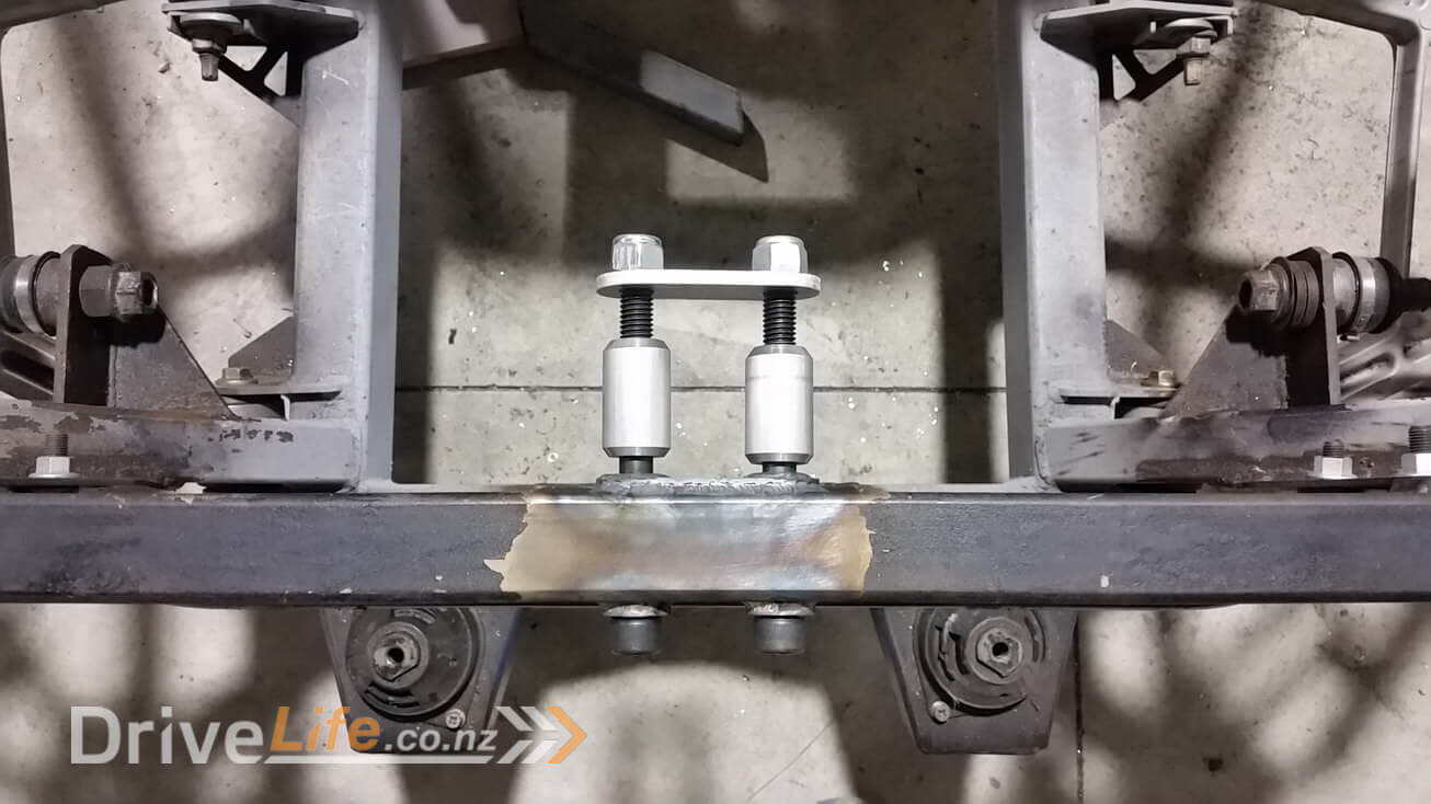
Next I needed to create somewhere for the actual coilover to attach to in-board of the chassis. In the interests of space, I tried to get the coil-over as far back as possible to give us space closer to the engine to allow the exhaust to come up and over later on in the project. I machined a couple of steel tubes that I could weld into the chassis and this would allow me to bolt the coil-over to the chassis.

Based on rough calculations before I started, and now that things are in place, this system looks like it’s going to work and finally got the car sitting on its own at last.


As mentioned at the beginning of the article, if you look at the photo’s and read my simplified version above of what happened it looks quite straight forward, but this whole process was close to 6 months or more to get to this stage !
There’s a newer entry in this story, please click here – FZ12 – Part 18
If you’ve missed the last part of our story then click here FZ12 – Part 16
or if you want to go right to the beginning then click here FZ12 – Part 1


Amazing work, been watching since the start, you are doing a lot of stuff I dream of doing, if only I had space and time, for the shock mounting to chassis are you going to support the other side of bolt or is there sufficient strength in bolt?
Thanks for the comment. It’s been a real learning curve for me to read and understand what might be the best way and then try to put it into place with the skills / tools I have available to me. To answer your question though, yes the other end was planned to have support with some struts that would go down to the chassis.
We believe in normal operation that the bolts would have been OK, however during high shock loads like large bumps there is a good chance they wouldn’t cope. We planned to have a plate between the bolts as well so technically it would double the load capability, but we felt it also needed more support to be safe.
Without saying too much, more will be revealed in the next episode ! Thanks for following.