


Projects like this just simply aren’t possible for your average person (me) if you don’t have a good bunch of friends around you. I would have never started this project if I didn’t have Zac on-board as I just don’t have the skills to complete all of the things we would need and didn’t have the funds to pay anyone either.
So far I’ve had Ash from Kaizen Works helping with welding and fabrication, Mitch from O.L.S helping with laser cutting and waterjet cutting, Liam, Simon and Barry from Melbar for CNC machining and now Lance is helping with his wiring knowledge…………..legend.
We started with planning. Sounds boring but it’s critical to go through every area in detail as once this wiring loom is all wrapped up in heat shrink it’s not realistic to modify it without some major work, so planning is key. Lance and I created a spreadsheet and planned out each function, its wire colour, the required load capacity, its pin number in the main connectors and a few other details, so you can appreciate that it took us both a good few days to get us to a place where we felt we could start.
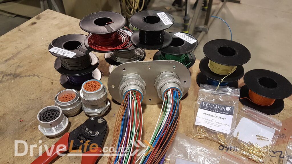
Next step was to measure and estimate the amount of each wire we were likely to need and get it all ordered.
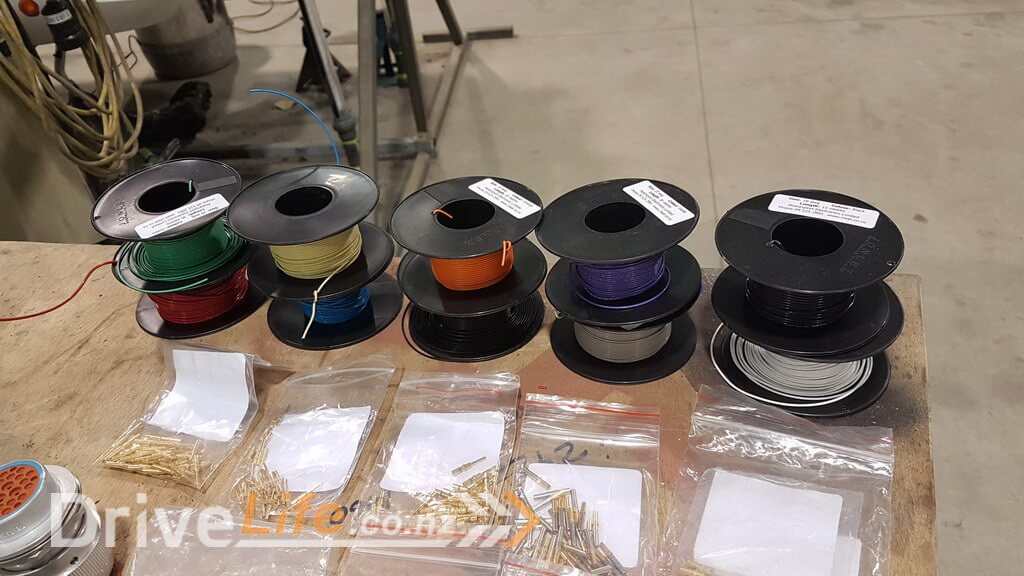
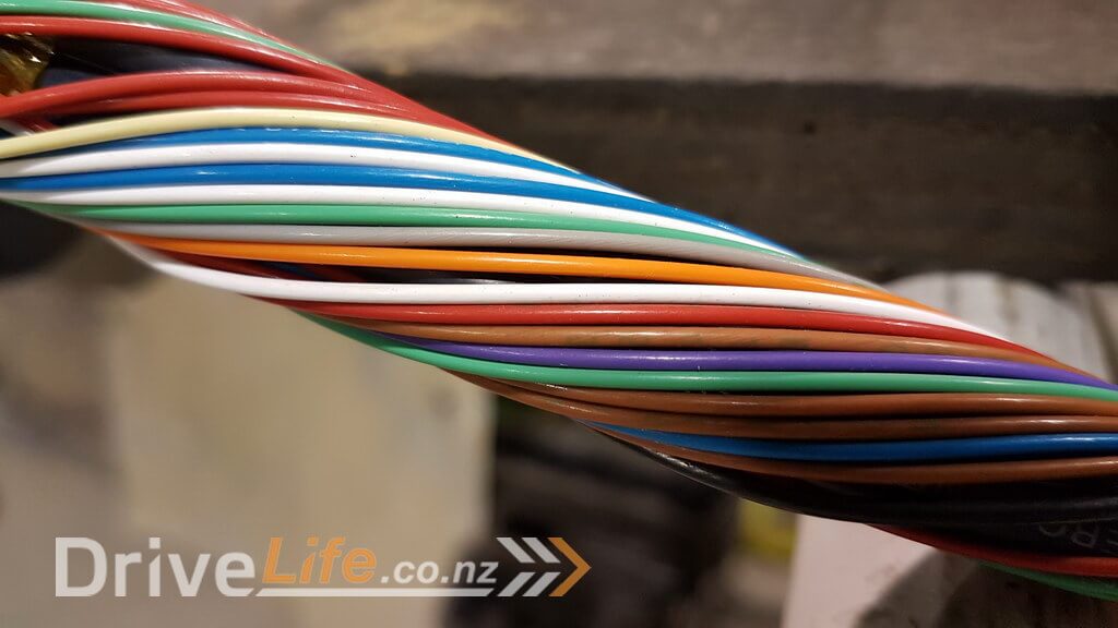
We are trying to build this loom to what some describe as “Milspec”. This basically is a military specification that a lot of motorsport looms are constructed to meet. The main reason to use this specification is that it is designed to allow flexibility in the loom, whilst being resistant to heat, abrasion, cutting and liquids, so ideally it should make it more reliable. We are using a wire called “Tefzel”. A lot of people believe this is more expensive than traditional wire, but in fact it’s very similarly priced, but is lighter, smaller and stronger, so with so much wiring required for this car, it’s going to make a massive difference.
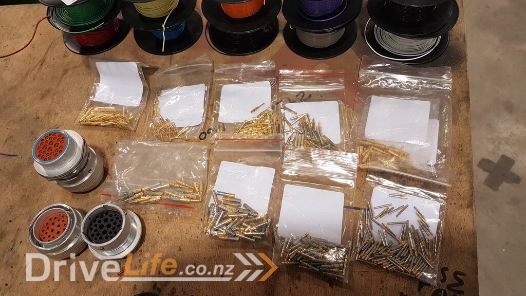
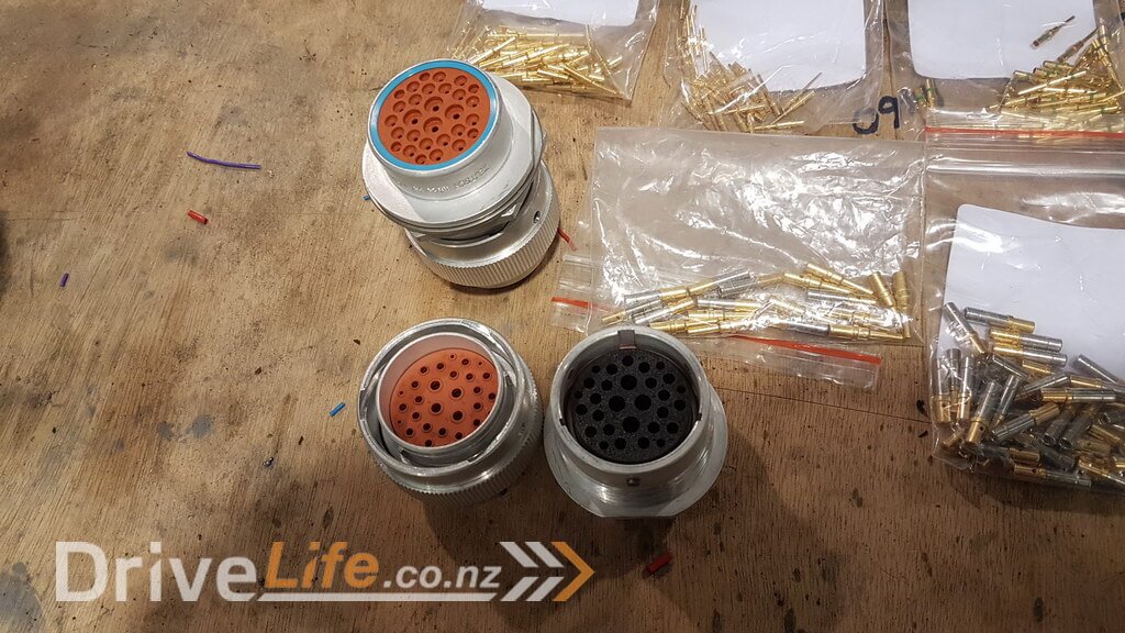
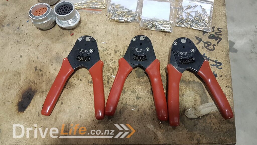
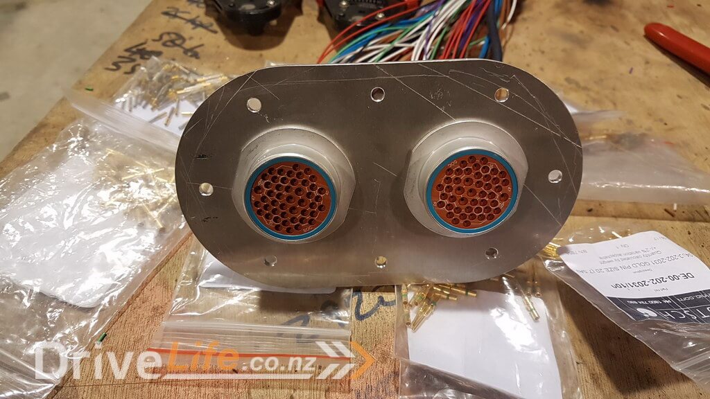
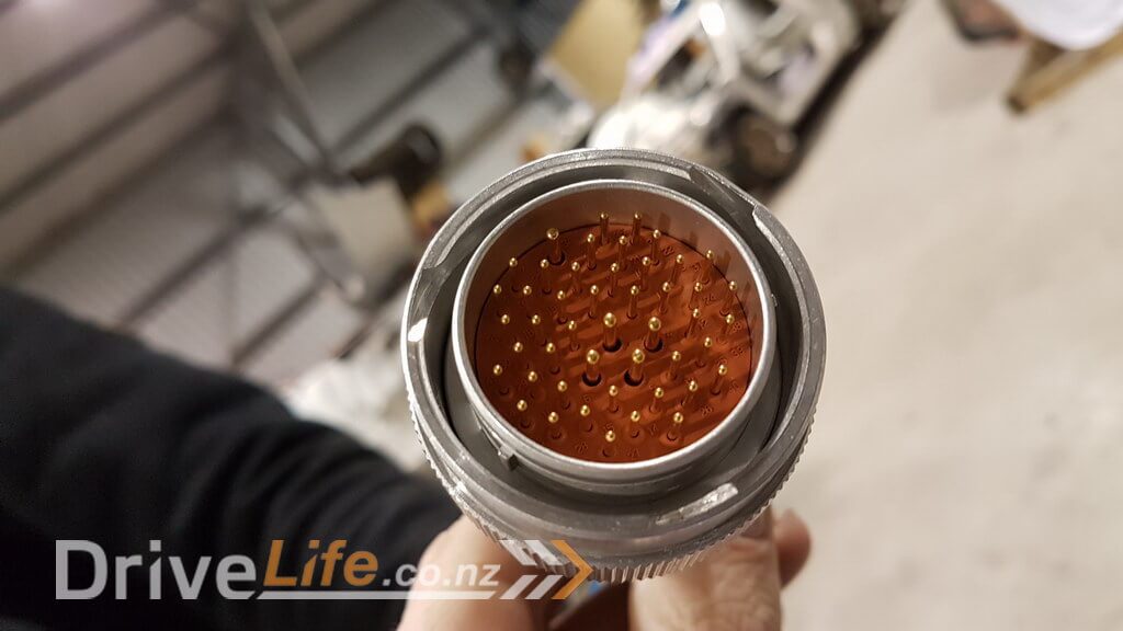
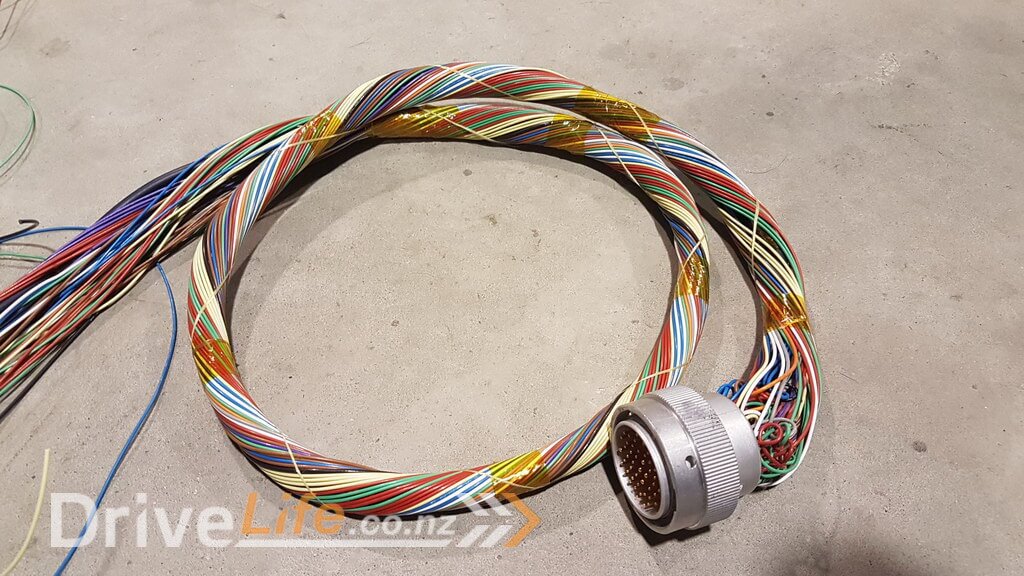
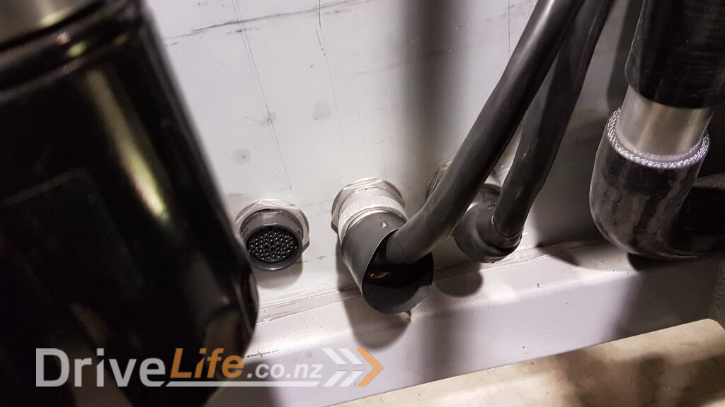
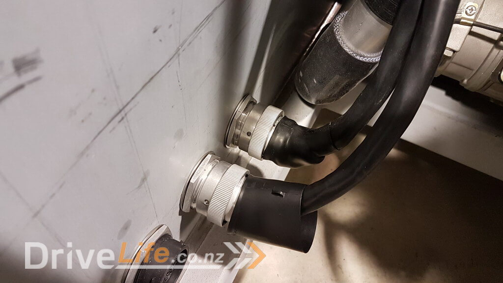
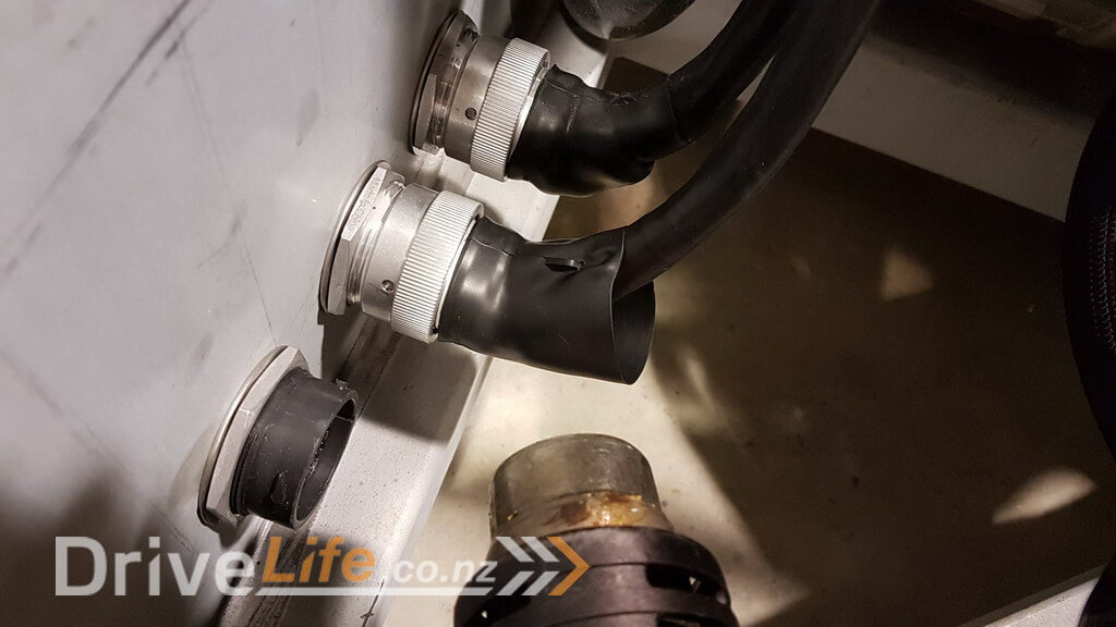
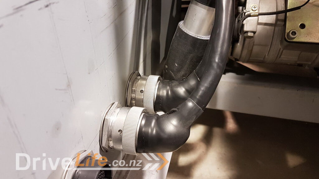
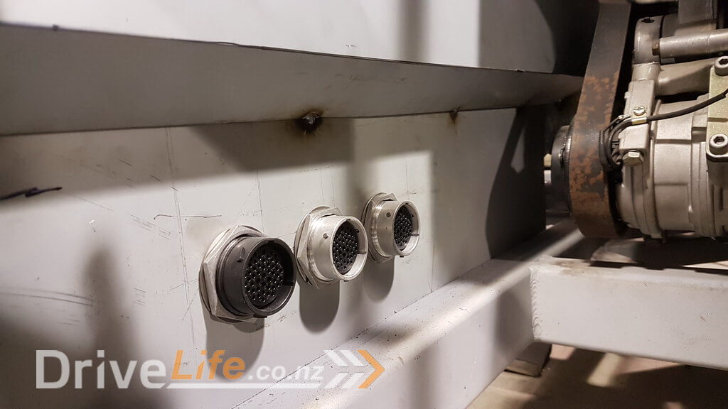
Our plan is to use the Deutsch HD30 bulkhead connectors, which again are industry standard connectors. These connectors are the large round connectors shown in the picture above and below that have real gold on the pins since it’s the best conductor and doesn’t oxidise like other connectors can over time. These pins need a special crimping tool which Lance already had from other projects he’s been involved in.
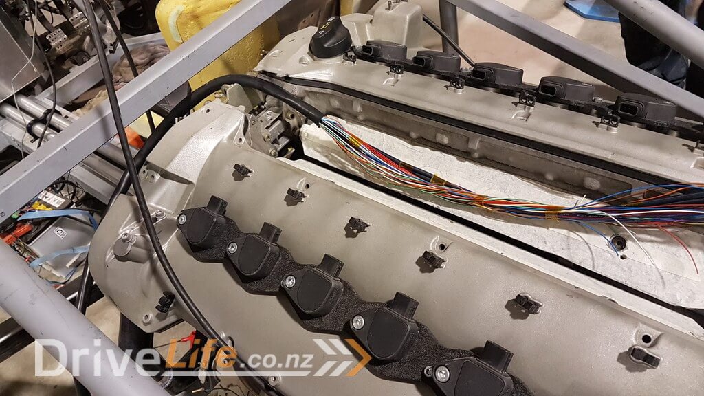
Since we had already planned out what we needed, then the process started to cut wires out to the right lengths. We mocked up a rough position of where the HD30 connectors would be once the rear firewall was in place and then proceeded to run wiring towards the engine and its sensors. We obviously left a little bit more wire than we thought we might needed so there will be some wasted later on, but that’s way better than having it too short !
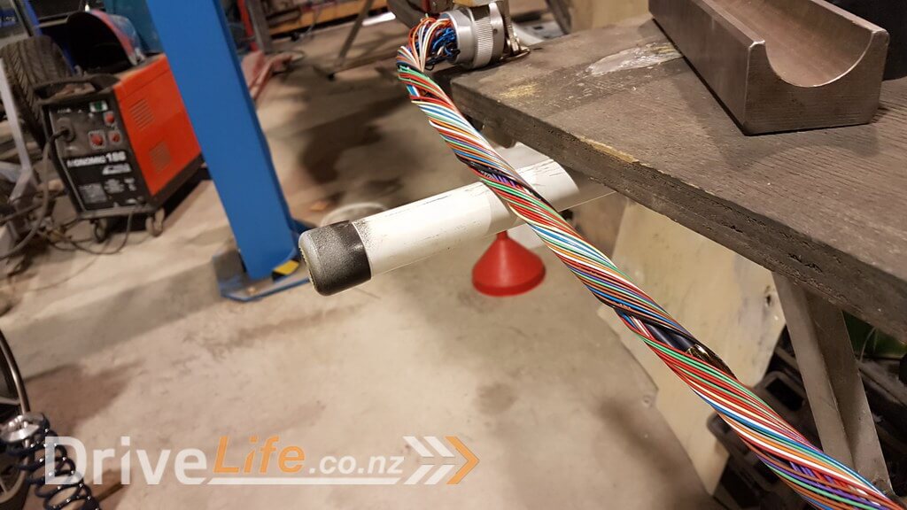
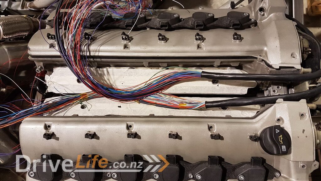
Once we’d got our rough measurements this is basically what we ended up with.
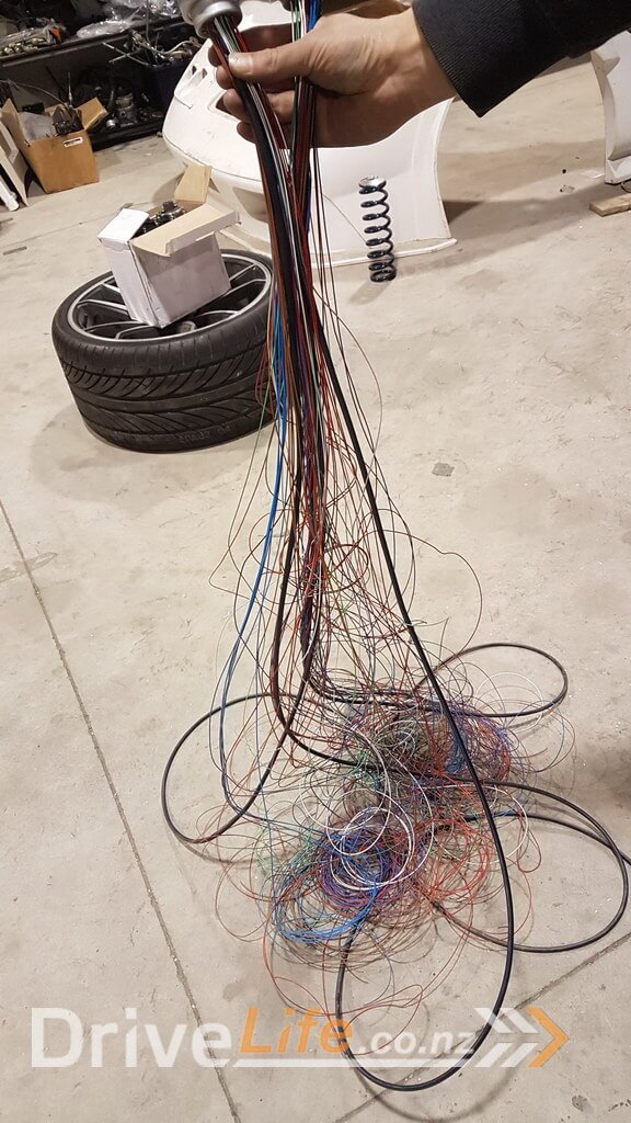
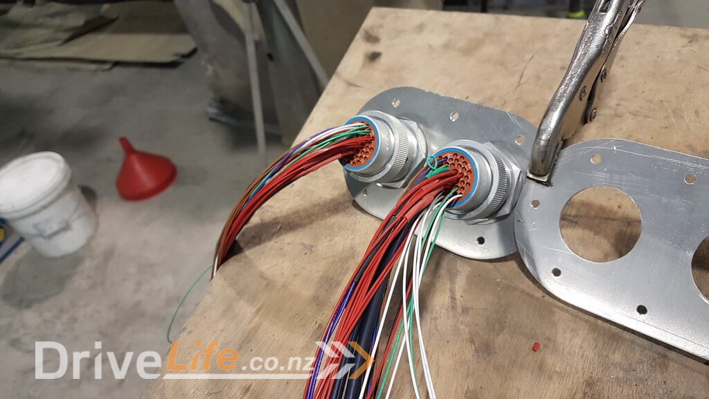
That is only about two thirds of the wires for the engine and less than half of the overall wiring so you can see already the size of the task ahead !
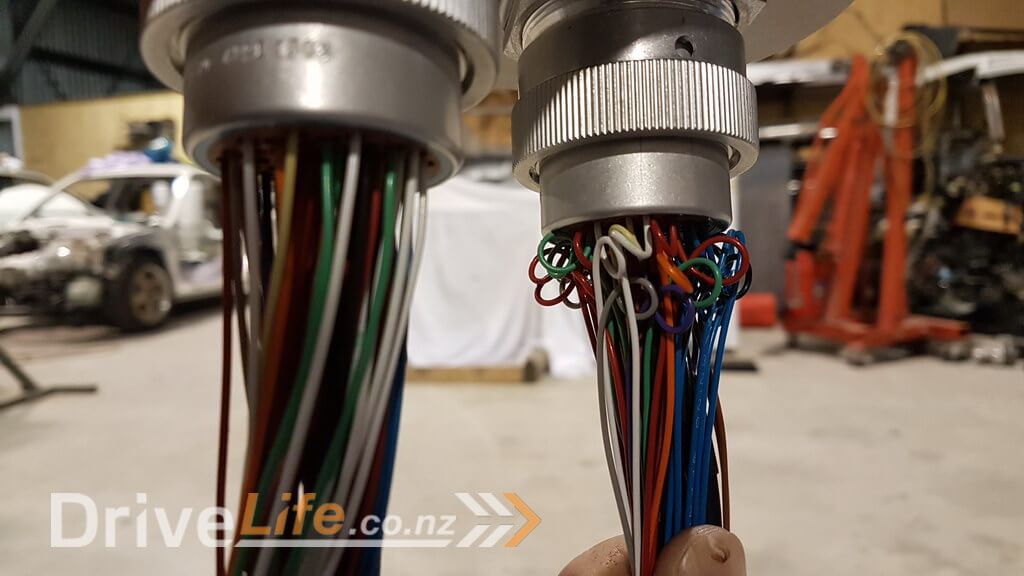
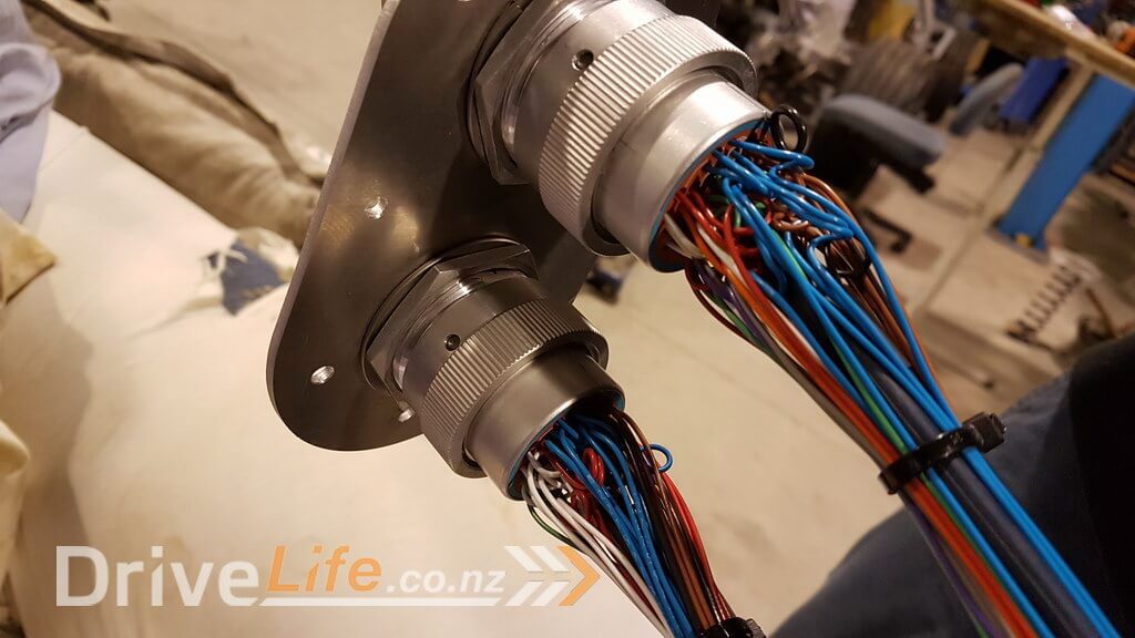
Something we included, but some don’t is are “service loops”. These are small loops in the wiring just before the HD30 connector pins. These service loops provide a few different benefits, however the main one is for reliability, as it means that the main loom doesn’t pull directly on the crimped pin and so removes the chances of wiring pulling out of the pins. The second most important feature in my opinion is that it also allows flexibility if the main loom needs to move.
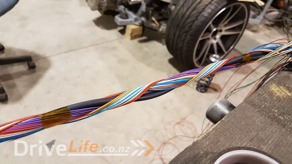
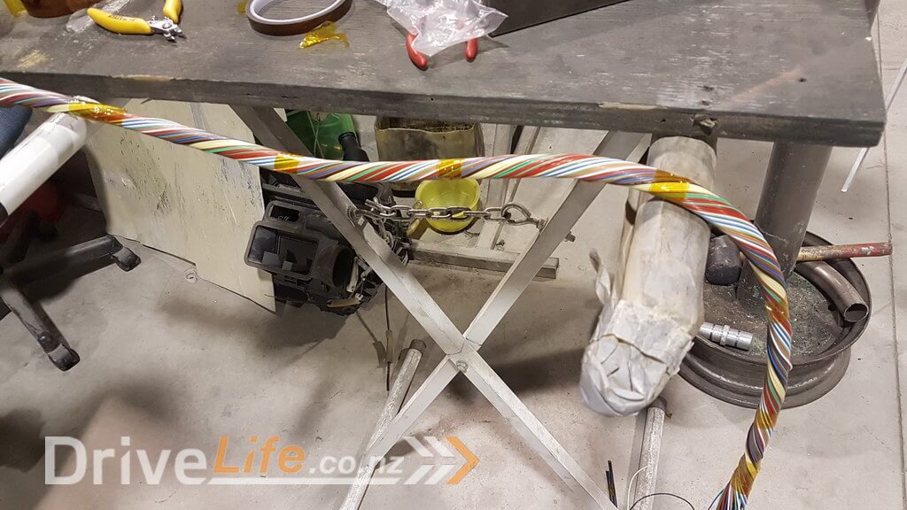
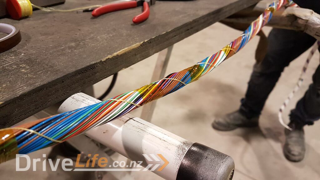
The next part of the specification we decided to use suggests that we use a process called “concentric twisting” which allows you to not only take up the smallest amount of space, but also protects the most sensitive sensor wiring in the centre, but most importantly allows great flexibility of the loom once it’s been covered. This is very time consuming and Lance and I spent many hours getting just the left and right engine looms twisted properly without any lumps.
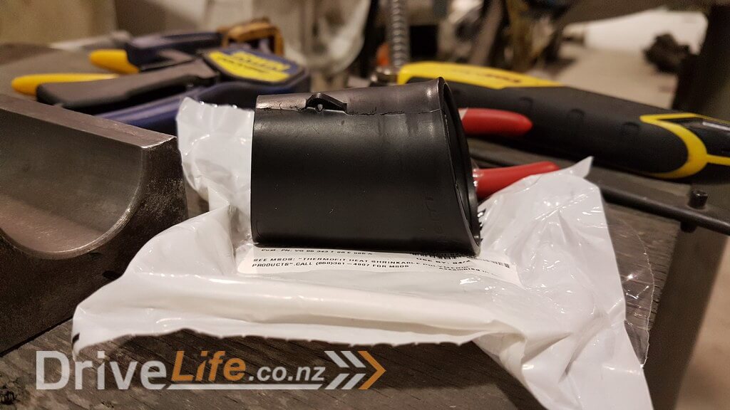
Next we needed to heat shrink the cable with a product called Raychem DR-25. This also meets the military specification. It’s like traditional heat shrink, but is much more heat resistant and much more flexible so really aides in allowing the loom to sit nicely.
We also needed to apply special heat shrink boots to the HD30 connectors. First we covered the wiring and service loops with kapton tape which is very heat resistant and thin, so is ideal for this job.
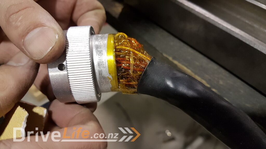
Next we start with what looks like a straight heat shrink boot, but in fact once heated it will be 90 degrees. If you look closely above you might also spot that we used sand paper to scuff the surface of the DR-25 so that the glue inside the heat shrink boot can bond well and seal the loom.
That’s it for this episode, but we’ve got plenty more wiring work to do, so we’ll continue this later.
There’s a newer entry in this story, please click here – FZ12 – Part 22
If you’ve missed the last part of our story then click here FZ12 – Part 20
or if you want to go right to the beginning then click here FZ12 – Part 1


Hi,
I am really enjoying read g about your project. It is very inspiring. I am trying to do everything myself and learning a lot along the way. I am building an old bmw 2002 with a BMW motorsport 4 cylinder motor here in Tauranga. I too want to rewire the whole vehicle and use a pdm unit… Is there any chance you would mind sharing your wiring diagram so that I can get a better understanding of how to do mine? Cad format is fine too.
Thanks Karl Oemcke 0275525425
Hi Karl,
Glad it’s been useful reading what we were doing. It was one of the main things I wanted to achieve as I enjoy reading other peoples projects also.
There’s absolutely no point me sharing our wiring diagrams with you as we have so much stuff that you wouldn’t have and the layout of the car also means that your wiring loom wouldn’t even relate to what we’ve done.
What I can suggest / recommend is that you start with an Excel spreadsheet that lists out all of your ECU’s inputs and outputs, then a seperate tab with the PDM’s inputs and outputs, then seperate tabs again for other things also.
This makes it really easy to just sit down and go through and fill it out with stuff you know you’ll need, headlights, wipers, ignition, ECU, injectors, fuel pump etc etc.
We found that even when we sat there and tried to think through everything we still missed stuff here and there, so just keep going back to it over and over and you’ll fill it all out nicely and you can record the wire colour or code you’re going to use and it’ll make it much easier to make your loom based on that.
I’m happy to e-mail you a blank version of what we used so you’ve got something to start with…… it’s honestly something you’ll need regardless, you won’t get anywhere without documenting it.
Also, I’d recommend that you have at least a few spare wires run for stuff you will forget and stuff that you might want to add later and having spares in different areas will save you so much time and effort later for the sake of a couple of extra wires here and there.
Hope that’s helpful.