


Welcome back. This episode is going to focus on the water supply from the engine, down the centre of the car to the front where the radiators will eventually be mounted, and then back up the centre to the engine.
First things first, reasons for mounting radiators at the front. So, as I seem to mention all the time with this build, space was a real issue and so mounting the radiators at the rear although technically would have been possible, I’m not sure it would have provided the cooling we’ll need for the V12 when it’s running at its peak. Also it would have been hugely difficult, not to mention potentially very costly.
Another main reason that I quickly discounted mounting radiators towards the rear was the weight balance. We already have more weight towards the rear than I would like and having radiators and plenty of water back there was just going to make things worse. Now the weight will be primarily towards the front or very low and centred which is a much better alternative.
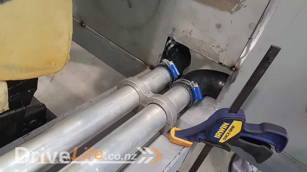
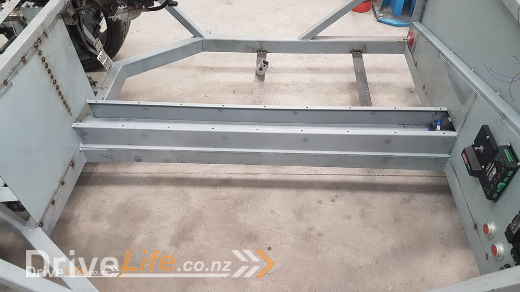
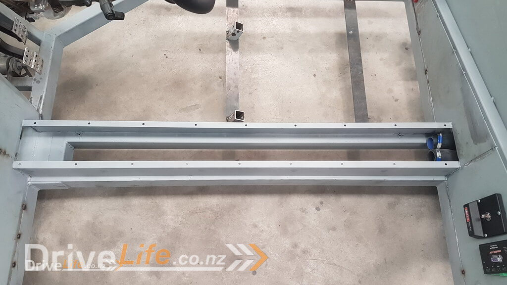
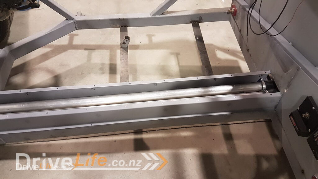
OK, so with that out of the way, I looked to a local supplier to find some 44.5mm aluminium tubing that would run up and down the centre. This seemed logical to me as it’s the same as our NSX and since that is also a mid engined car, there didn’t seem any reason to do anything different.
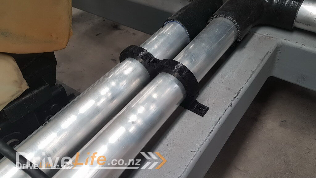
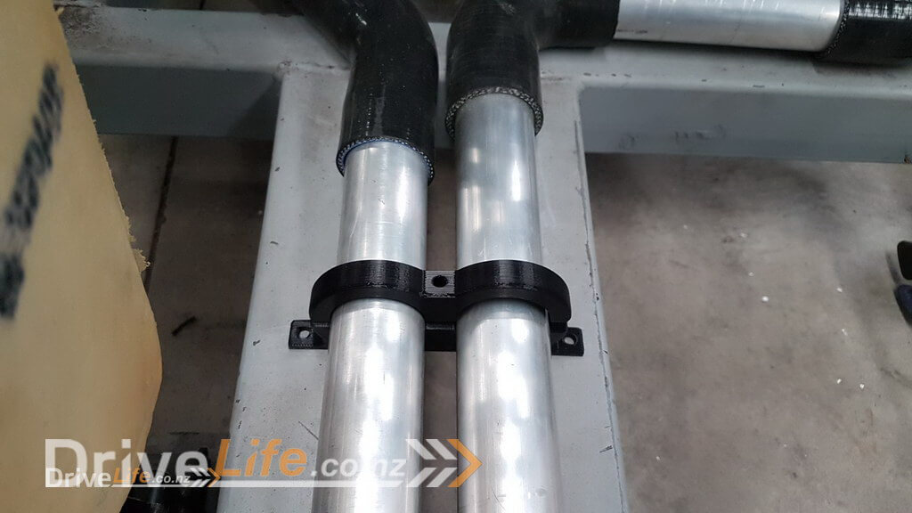
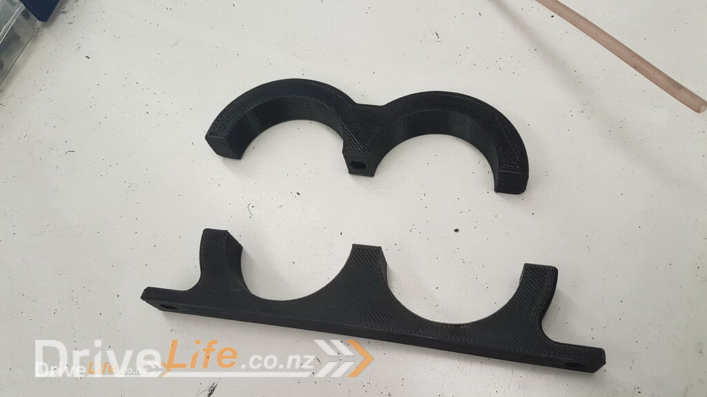
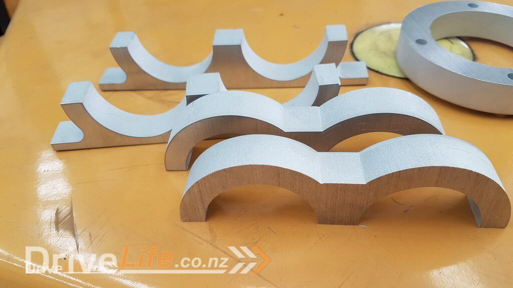
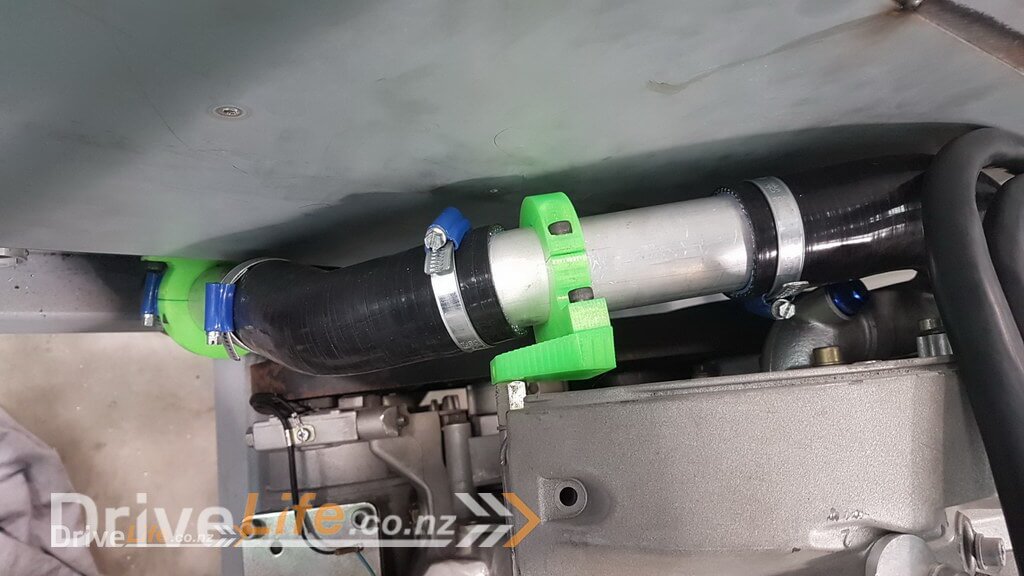
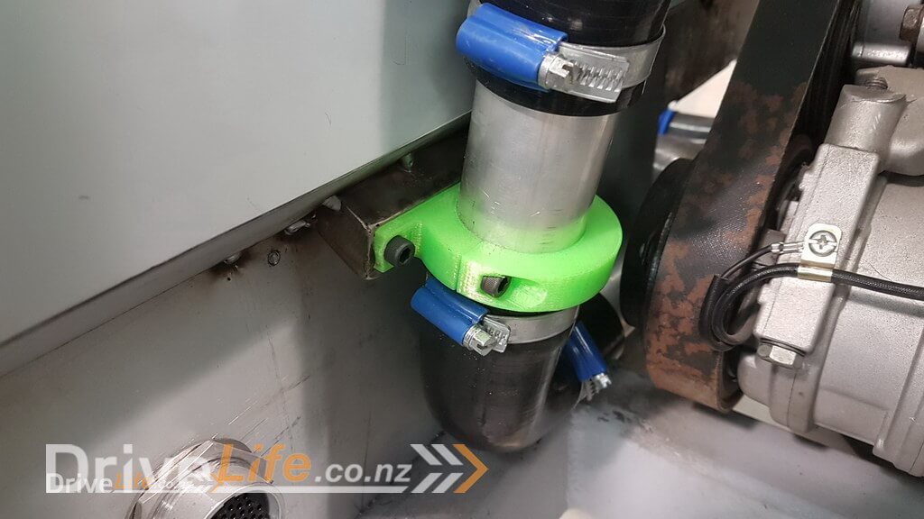
Now you may have spotted that I’ve been using my most used tool in this project so far my 3D printer to create some clamps to hold the pipes in place. They’re obviously nothing too complex, but since I have access to a CNC machine and the guys running it are always keen to help with the project it seemed like a no brainer !
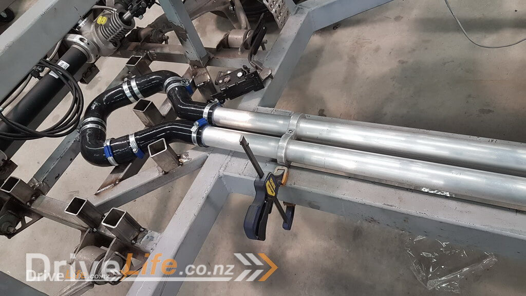
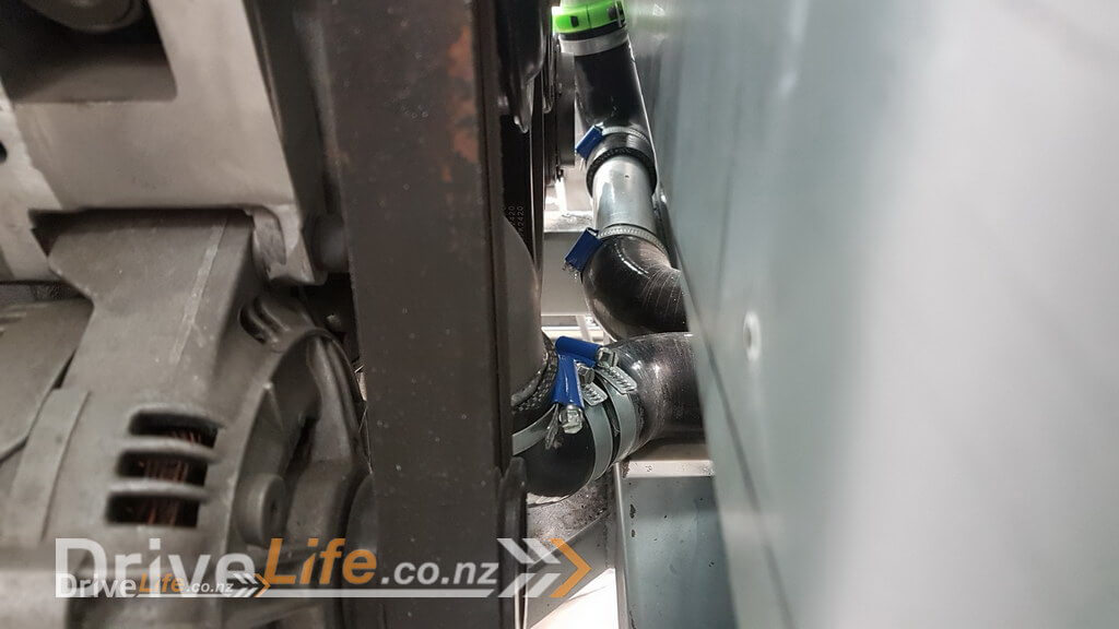
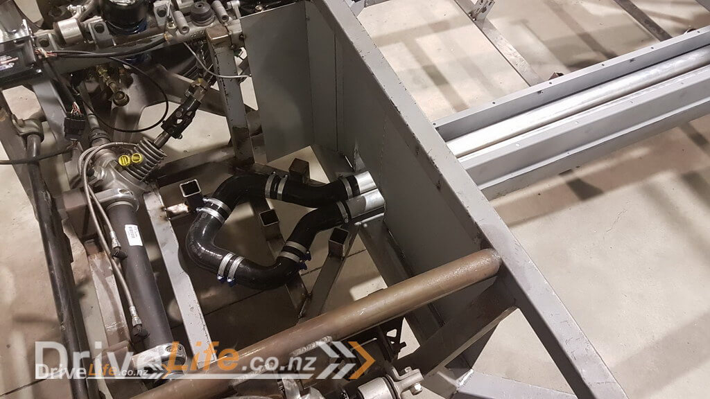
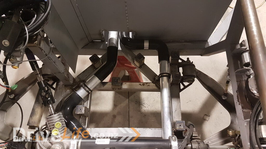
Now that I had the main pipes sorted, I needed to connect from the engine down to the main outlet pipe and return pipes that we just ran. The main outlet and inlet from the engine required some small modifications to change its angle a bit as we needed to mount the engine so close to the rear firewall that it was going to be too tight. This was easily sorted by putting a cut into the existing outlet, changing the angle and then welding it back together. Once we had the space, it was just a matter of using some silicone hoses of differing angles and some short sections of pipe to route around the other engine parts and then connect to the centre. You can see the 3D printer came in handy again also !
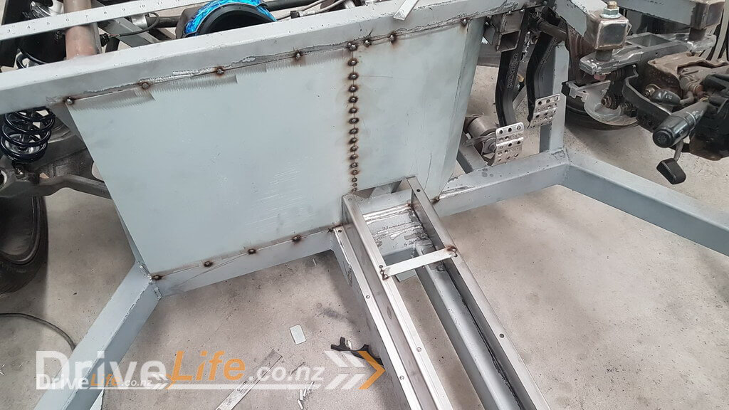
After trying to think a bit further forward in the project, I realised that I needed to make the water pipes and also the fuel lines (this will be covered in a later episode) in a tunnel that was effectively the underneath of the car to make sure that if there was ever a hot water or fuel leak that it wouldn’t be able to find its way into the cabin. Not only is that common sense, but I’m sure it’s all covered in the “Low volume certification” rules that we’ll need to pass to get this thing legal once we’re done.
I decided that even though the plan is to have a composite style tub in the centre, that it still made sense to have a thin sheet metal firewall front and rear. Although this will add a small amount of weight, it was required in some places and it was going to be too “patchwork” to have some metal here and some fibreglass there. It seemed so much simpler to just run a metal firewall and then we will fibreglass over it later to create a single tub.
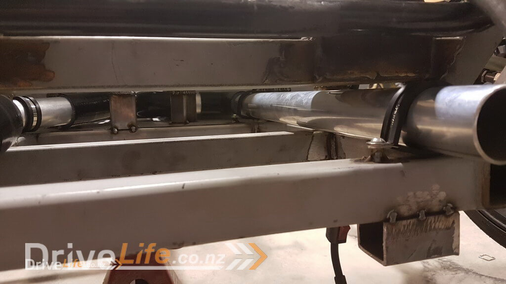
Being metal, it also helped with the design of the centre tunnel as I was just able to get OLS to laser cut some flat sheet with holes already cut for welding the bottom and to be able to bolt on the top. Then the guys from Melbar engineering put it through their CNC bender and turned it into a Z shape for me. Then it was just a matter of putting one on each side trimmed to length and welding in place. The welds look really dirty as I actually put down some sealant underneath the tunnel before welding to help seal the tunnel and some leaked into the weld sites unfortunately, but it won’t affect either the weld or the sealant so all good in the end.
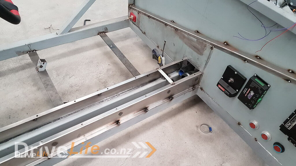
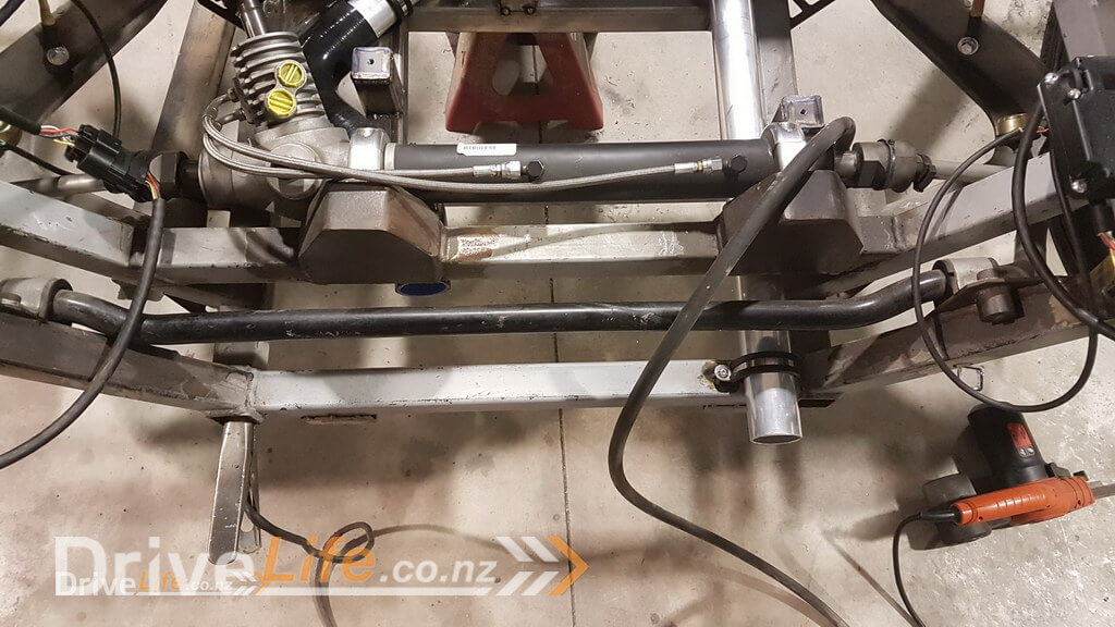
It seems that with quite a few things in this project I have a plan and then whilst working through one thing I realise that I need to do another thing first. This tunnel was a good example of that, having to do the firewalls before I did the tunnel when I hadn’t planned to, and then the front part of the water pipes was another. I had planned to just join them up temporarily like this.
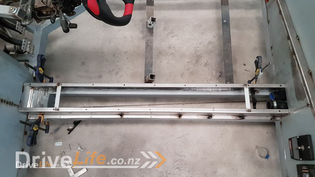
The intention was that we just wanted to get everything in place to be able to get the engine started and a very basic tune put in place to make sure the engine itself was fine after sitting for so long and to also make sure we were happy with things like the wiring etc also. So we weren’t going to need the radiators in place to do that since we felt it wouldn’t get hot enough to need them in place. However, once I’d done the above with the water pipes I realised that I needed to continue the water pipes further forward to make space for the fuel pump, tank, hard fuel lines etc that I’ll need in place for the engine testing also.
So I started to run the water lines out and intended to run one to each side of the front compartment and all was going well until I realised that the steering rack on the drivers side (right) stuck down about 15mm more than on the left side, so I had to then route around that .
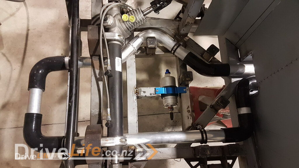
So now that’s given me the space to get started mocking up and mounting the fuel lines. That will be the next episode I think.
Thanks for following our build.
There’s a newer entry in this story, please click here – FZ12 – Part 24
If you’ve missed the last part of our story then click here FZ12 – Part 22
or if you want to go right to the beginning then click here FZ12 – Part 1


