


Welcome back.
In this episode I’m going to cover mounting of the power steering, ride height control and ABS pumps. To be honest when I started this process I didn’t really have a strict plan so there was a lot of standing around looking important and trying to figure out the best use of the space whilst still thinking about servicing and accessibility.
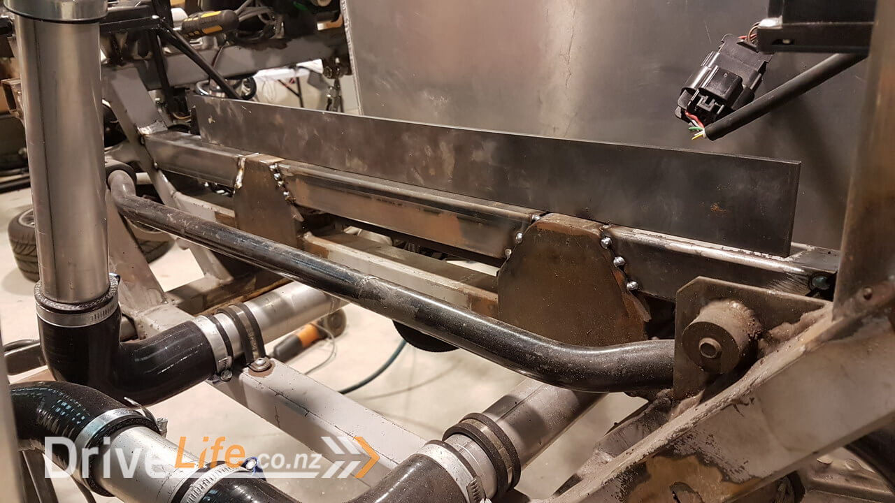
I started by adding some extra bars between the mounts for the steering rack. This would give me a nice flat surface to mount all of my pumps whilst leaving space for the front trunk / boot.
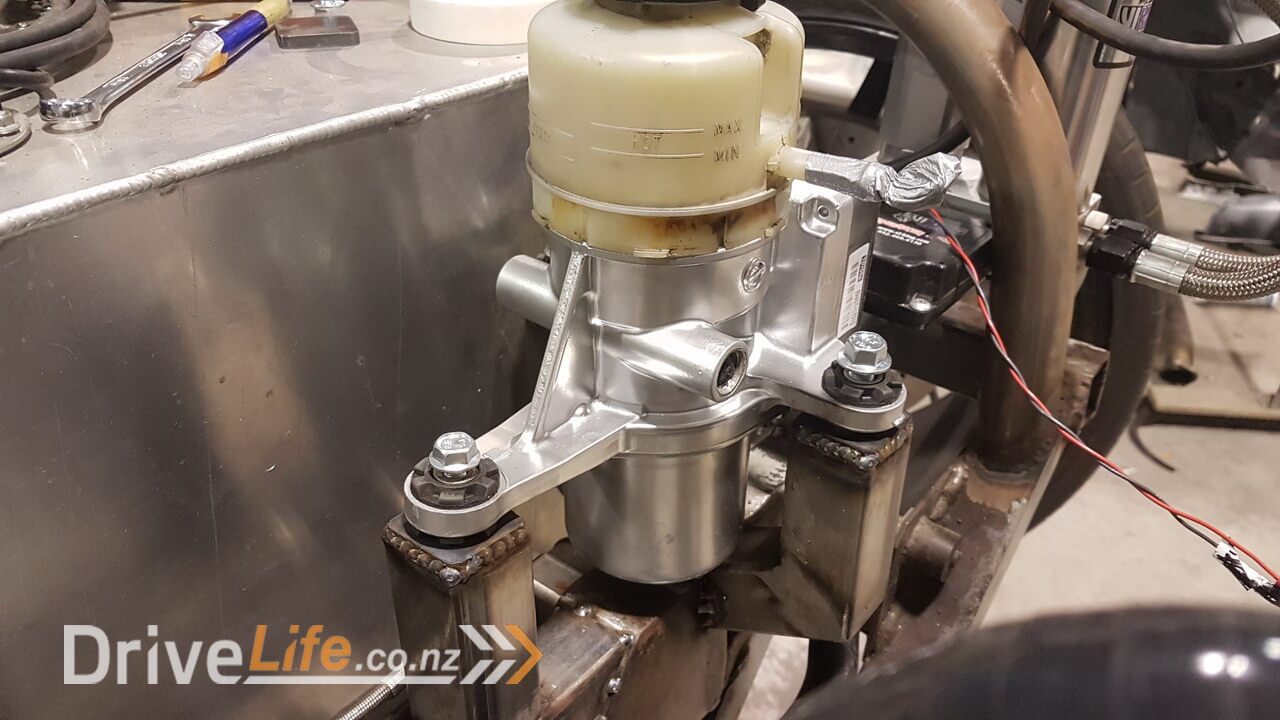
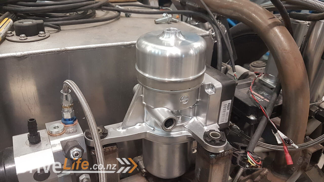
I started with the power steering pump. This unit is a really great unit and is quite commonly used with people building scratch builds such as this, or even just wanting to easily add power steering to a car that isn’t driven from the engine. This Toyota MR2 unit has the pump, reservoir and control electronics all in one unit. I could have possibly used some smaller bar to create the mounts for this, but it is a heavy unit and I used thin wall steel to keep weight down, but I thought it would look better in this size to match the other bars around it.
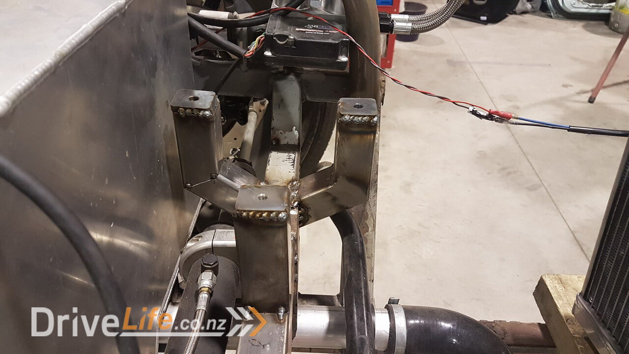
The two side mounts are even, but the third mount has an angle on it that doesn’t show in all photos, so there was some trial and error.
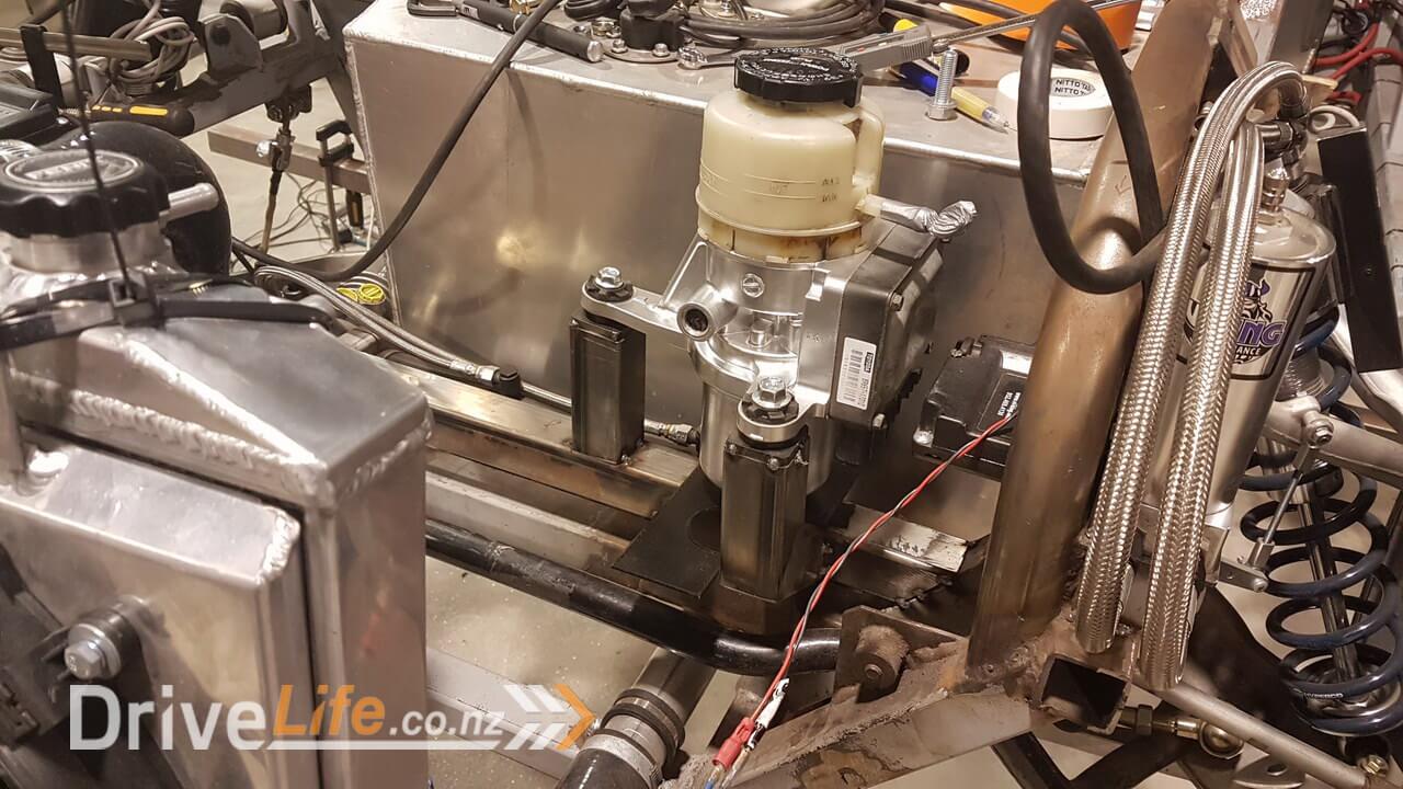
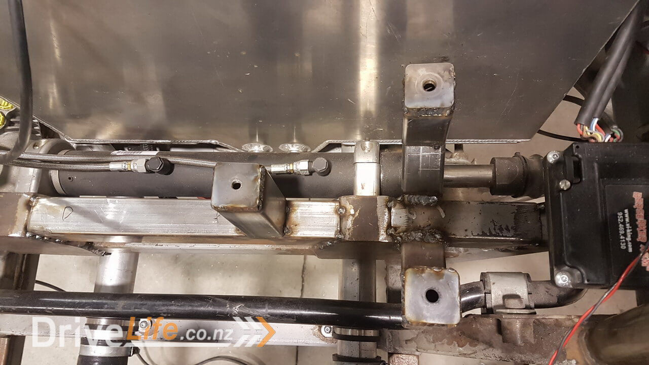
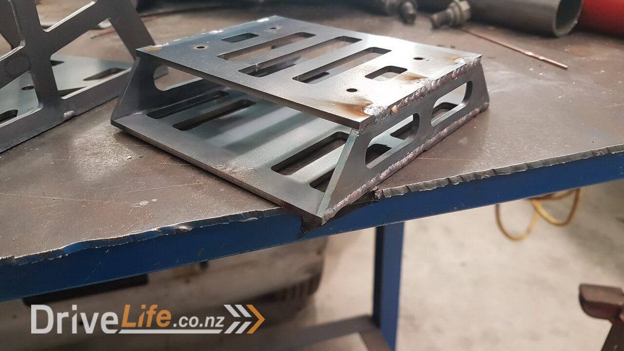
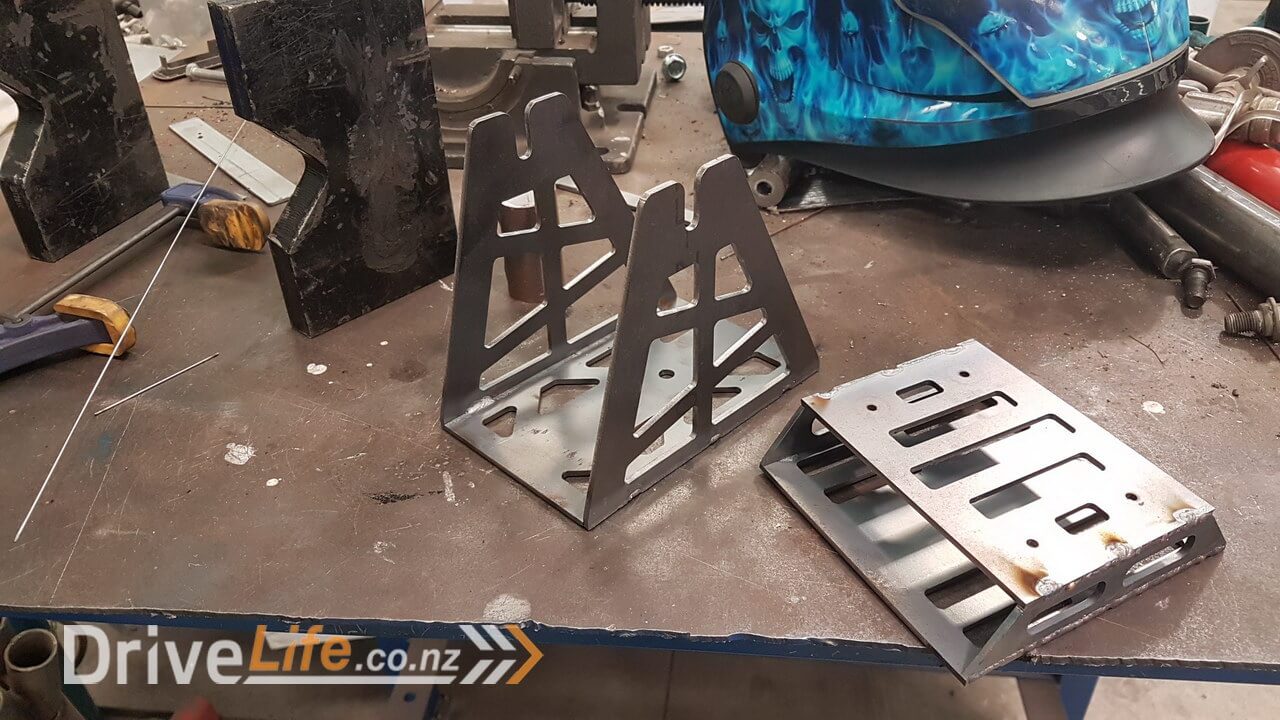
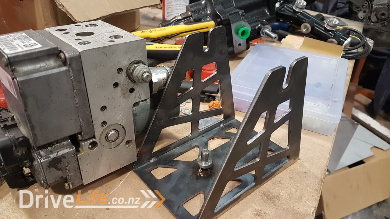
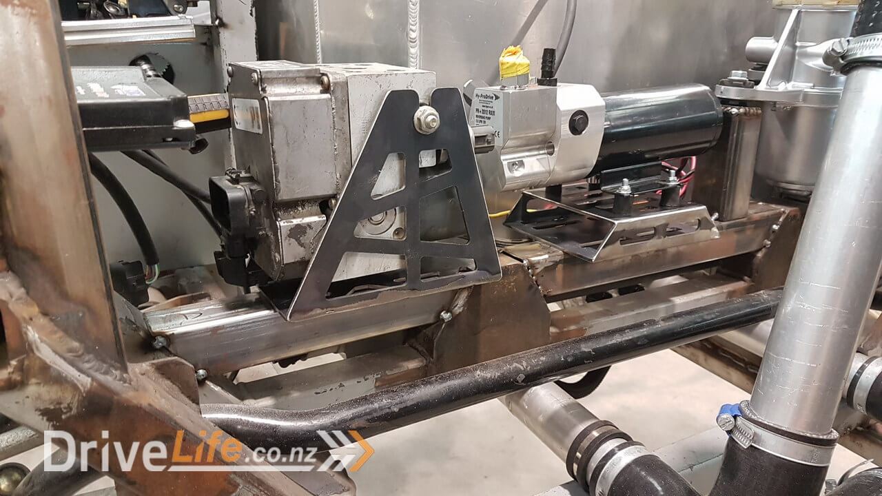
Next I needed to mount the hydraulic pump used for the ride height control system that I purchased and then developed for our needs. This pump feeds both front and rear suspension so I needed to allow to be able to get the hydraulic lines from both sides. I know I seem to say this a lot, but I started with a 3d printed model and tested and then O.L.S laser cut the final parts.

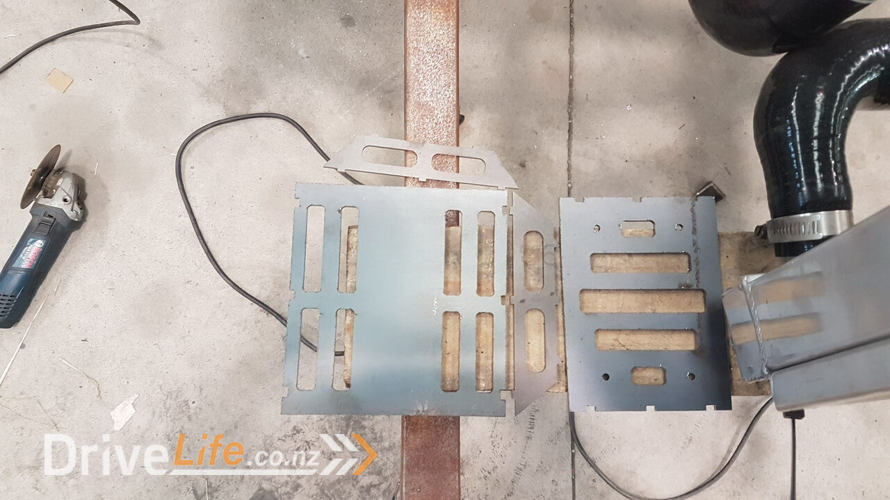
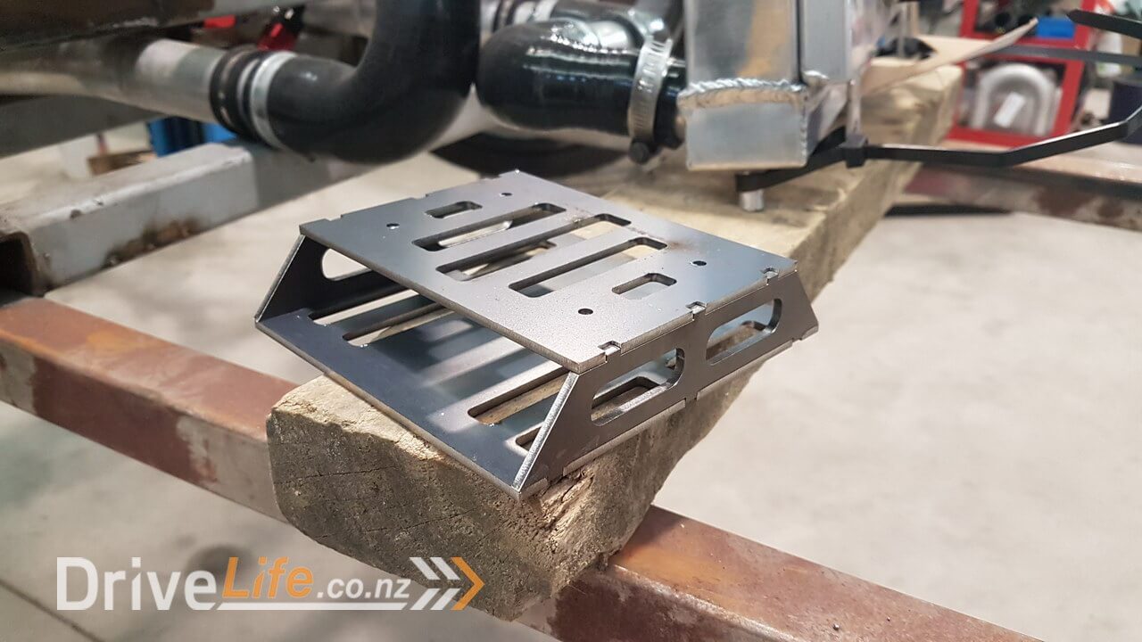
That was really just a simple base to give me a wider area to mount the ride height pump. Zac worked some welding magic.
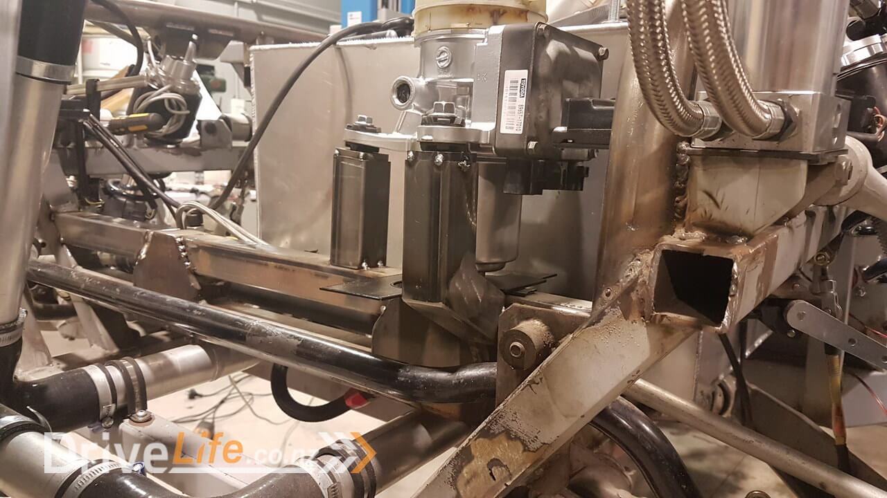
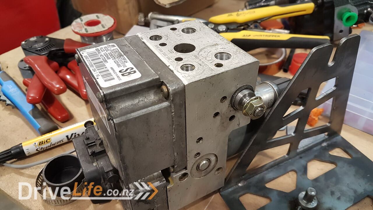
Next it was pretty much the same story with the Corvette C5 ABS pump. This unit already has its own integrated rubber mount design, but unfortunately two of the pins that held the rubber mounts were missing so I had to use my limited lathe skills to make two new ones, but they were pretty good and worked as I wanted.
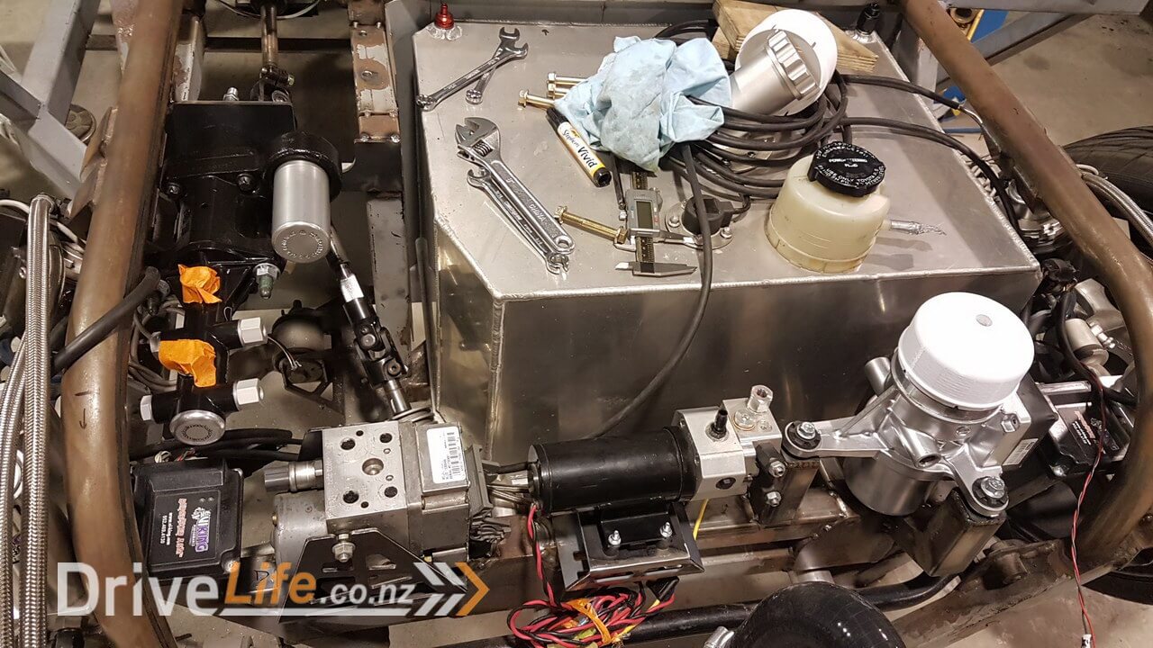
So all in all I felt quite a successful few days (yes it was a good few days work). Everything is rubber mounted so hopefully that will help with noise from the pumps travelling through the chassis, but also should mean we don’t run into any stress issues.
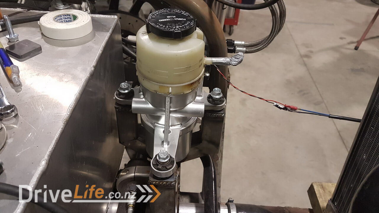
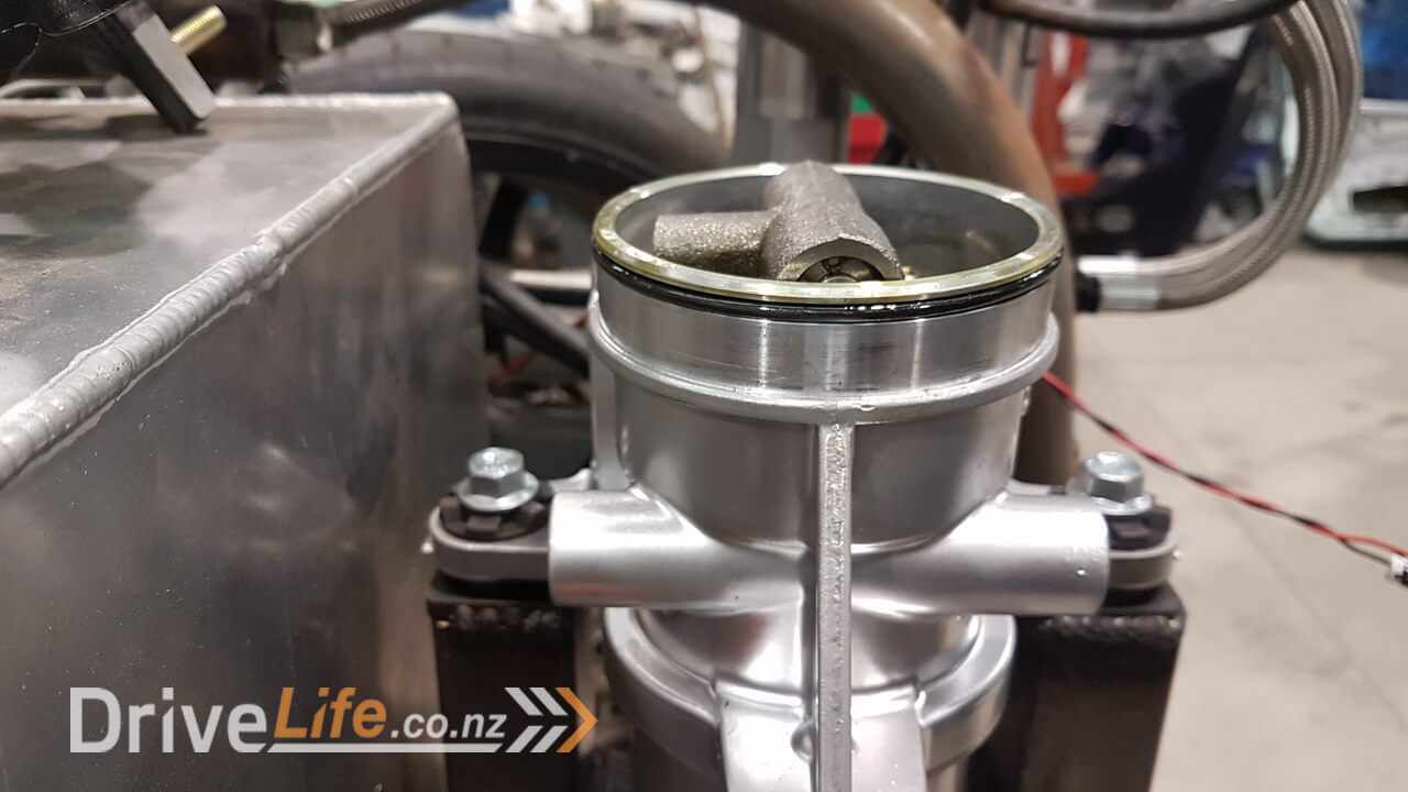
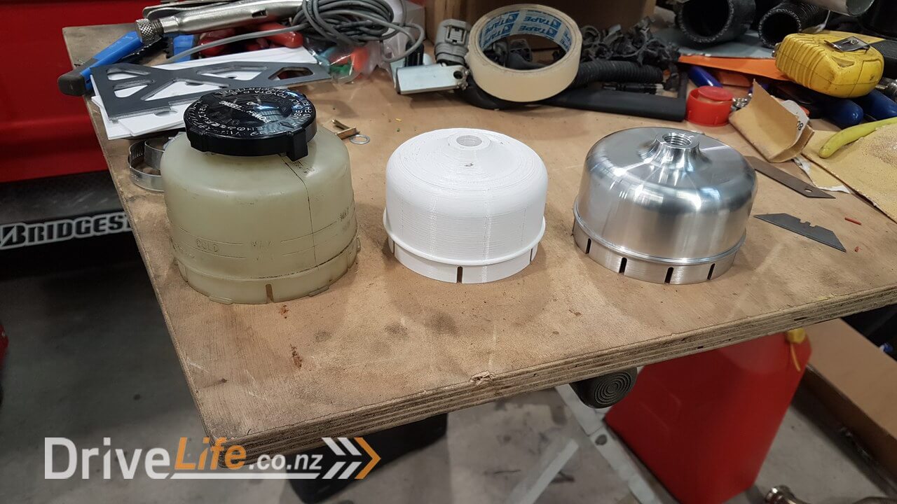
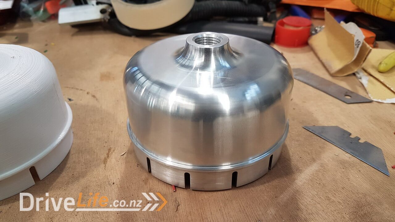
You might notice that the reservoir on the power steering pump is a 3D printed unit. This was for the same reasons that I outlined for the clutch master cylinder in the last episode. We plan to run remote reservoirs for fluids for all of these pumps so I needed to remove the factory plastic unit and replace it with something that would allow us to use AN type fittings with braided line.
Here you can see the progression from the factory unit, 3d printed model and then CNC machined aluminium unit. The final part looks amazing thanks to Melbar Engineering once again.
Please feel free to comment or ask questions, I really love sharing and discussing our build and cars in general with other readers.
There’s a newer entry in this story, please click here – FZ12 – Part 38
If you’ve missed the last part of our story then click here FZ12 – Part 36
or if you want to go right to the beginning then click here FZ12 – Part 1


