


First of all I have to start with apologies for the lack of articles over the last 6 weeks or so. Unfortunately real life took over from car life and I simply wasn’t able to post progress, but I’m back now and ready to report !
We’re getting close to having the “mechanical” side of the build done. There will of course be small amounts of fabrication to be done to mount the body etc and roll cage bars for the windscreen and roof but they’re fairly small and we can’t do them until the body is on.
The last parts of the mechanical puzzle is to mount the new brake booster (which this article will cover) and then accessories such as power steering, ride height and ABS pumps. Then there is the aircon evaporator and brake / hydraulic lines and new radiators……..oh man, that’s actually quite a list !
With all that said, there’s no other way than to keep plugging away. Unfortunately sometime our schedule is driven by when parts are arriving but this time I have what I need. Originally we were going to use a Corvette C5 drum / vacuum based brake booster. This was because we are using Corvette based suspension, brakes, ABS etc so it was common sense to try and use their brake booster also. Unfortunately for us, we simply don’t have the space for the Corvette unit so I needed to start looking for a new solution.
After spending numerous days hunting around for a smaller drum / vacuum based booster I came across a similar issue I’ve dealt with lots in this project. I know what I need physical size wise, but everyone you deal with just wants to talk part numbers or chassis numbers and doesn’t have the info when you say you’re looking for a brake booster with a 300mm diameter for instance. It’s really frustrating, but understandable that suppliers don’t have that level of information.
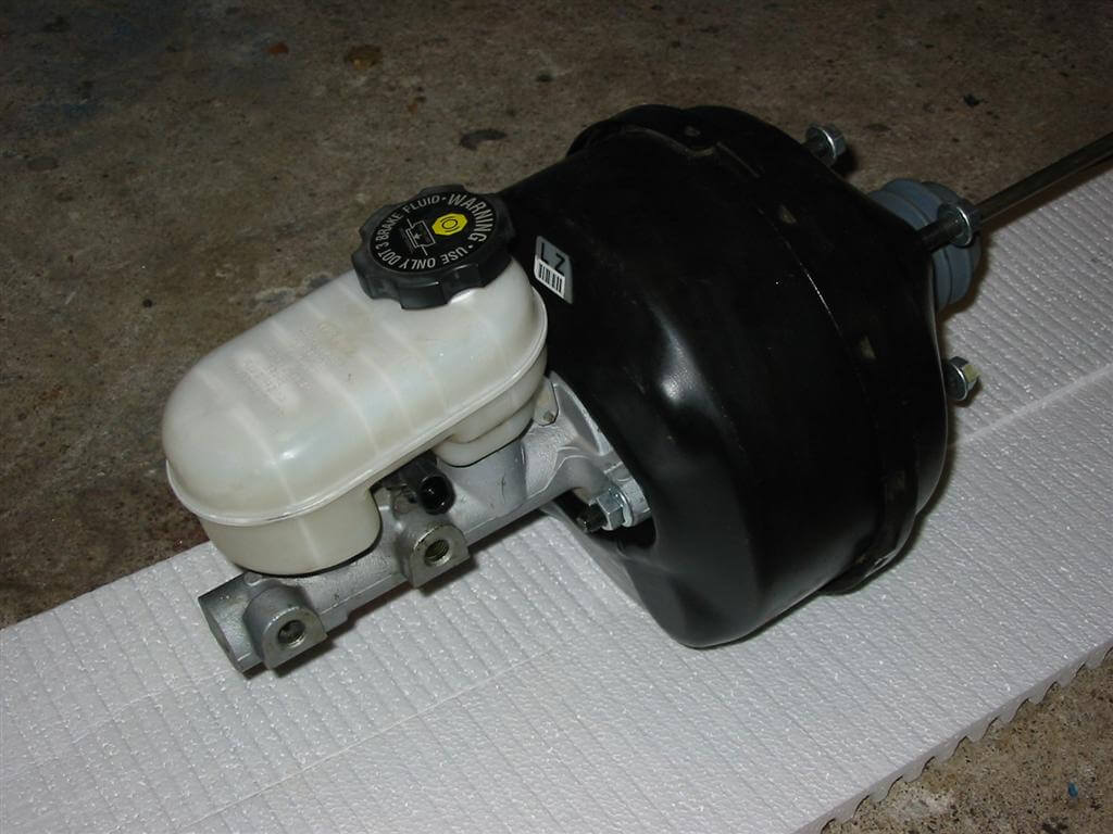
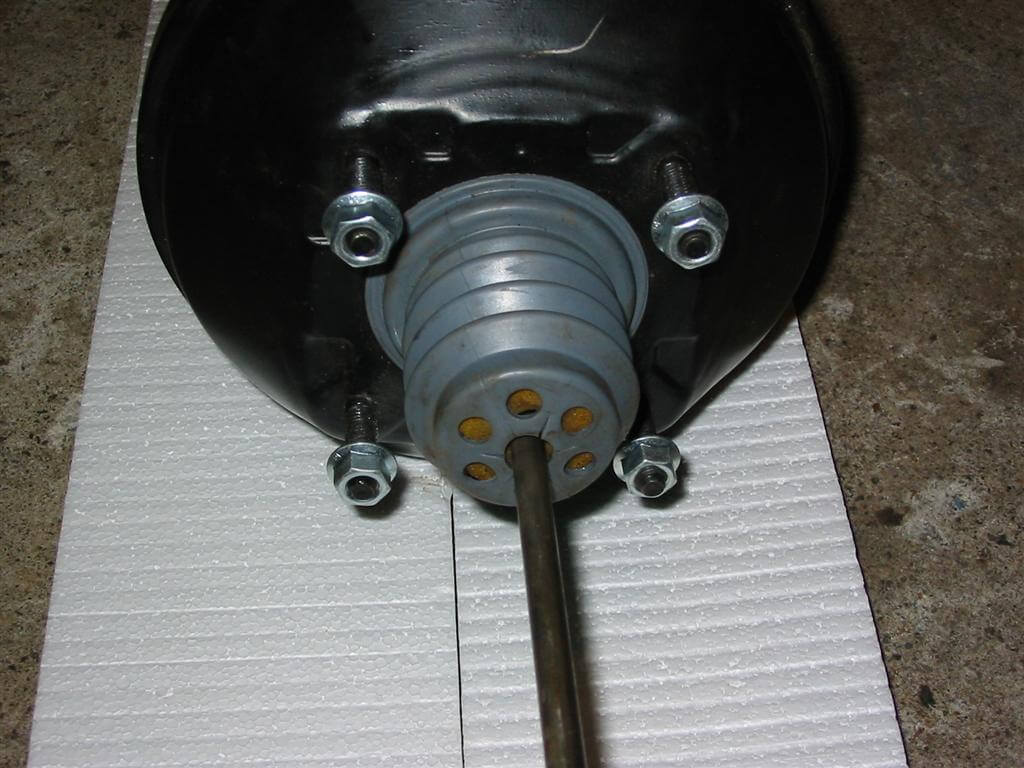
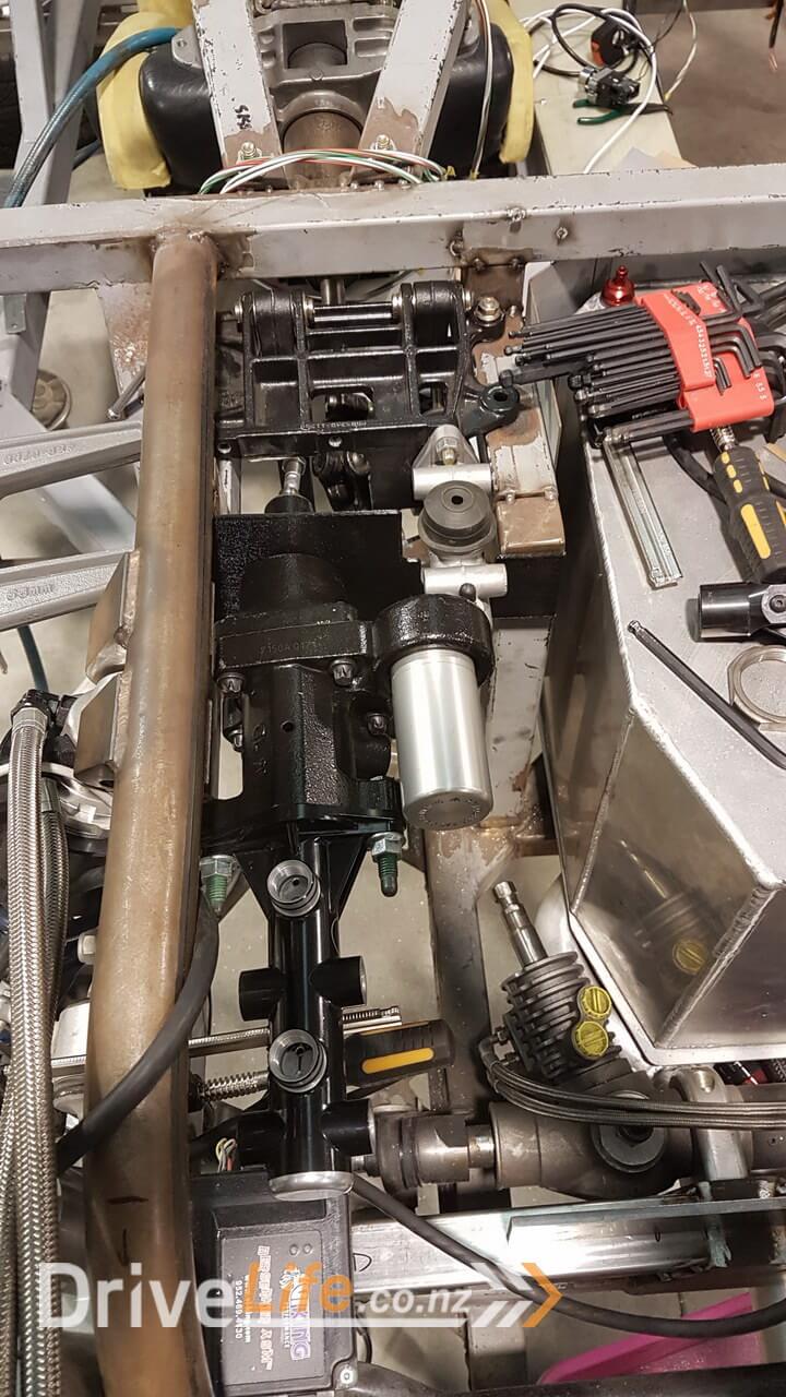
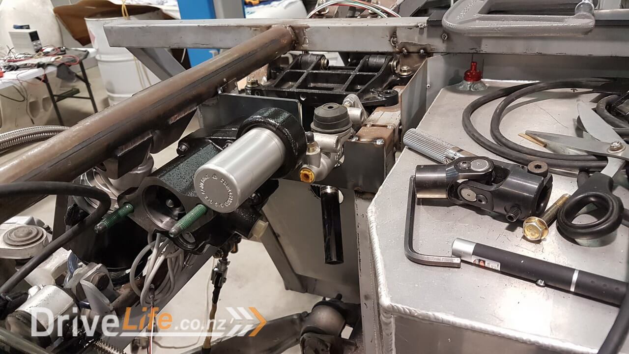
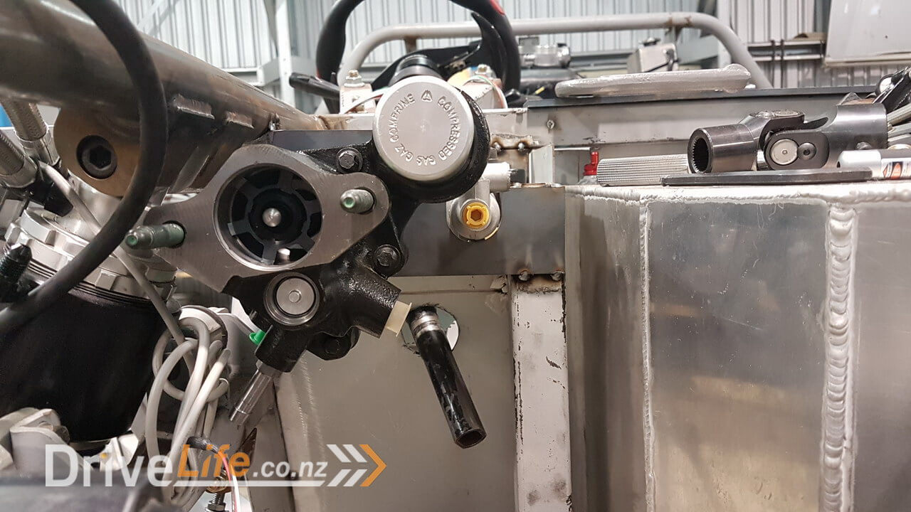
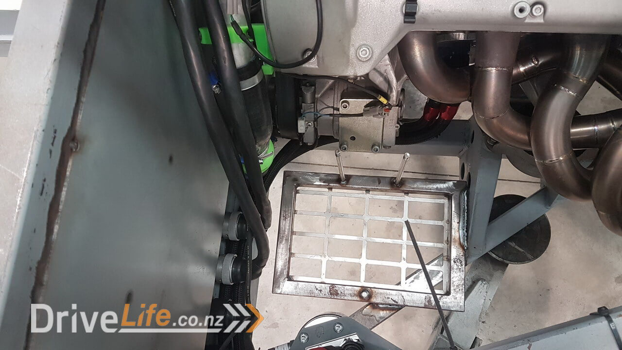
Luckily in this scenario it made me investigate alternative methods to boosting the brake forces and I came across a company called Powerbrake Service. They are specialists in building and servicing a Bosch design of hydraulic brake booster which is smaller and more flexible than the normal vacuum based boosters and also allows you to boost the brakes without needing to lift the throttle to build vacuum since it’s powered by the spare hydraulic capacity from the power steering pump.
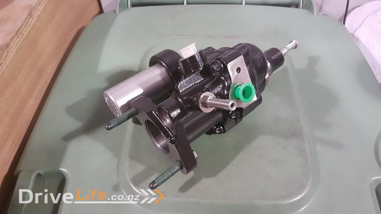
You can hopefully see the small silver cylinder in the photo above. This is charged with compressed gas and is charged by the pressure from the power steering pump. Instead of the hydraulic fluid going from the power steering pump to the steering rack and back to the pump, it first comes to this pump as normal, but then goes to the booster and then back to the pump. This means the booster can recharge if needed from the excess pressure from the rack and so doesn’t effect the rack at all and doesn’t put any extra load on the pump. Simple.
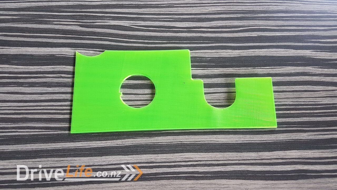
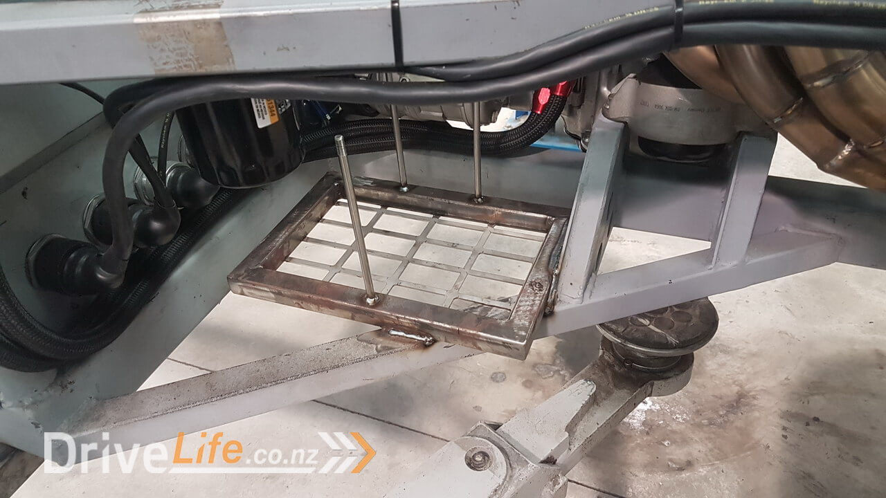
So first I needed to make a mount for the new booster. Even though it is physically smaller than the Corvette booster it is quite heavy so will need a strong / well supported mount. I started with your traditional cardboard template and then once I had it close I drew up something to 3D print as I needed something a little bit more sturdy to get closer to the final shape.
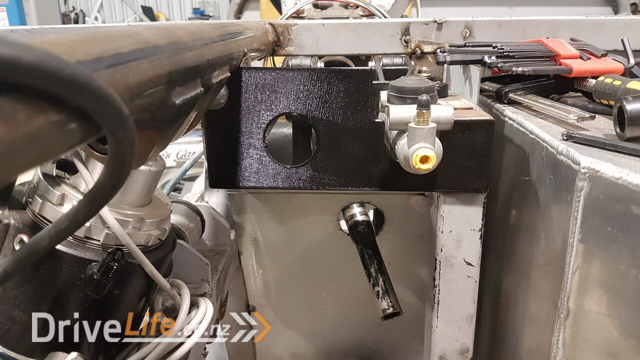

Next I went to our friends at O.L.S to laser cut my model from 5mm steel and I tacked it in place.
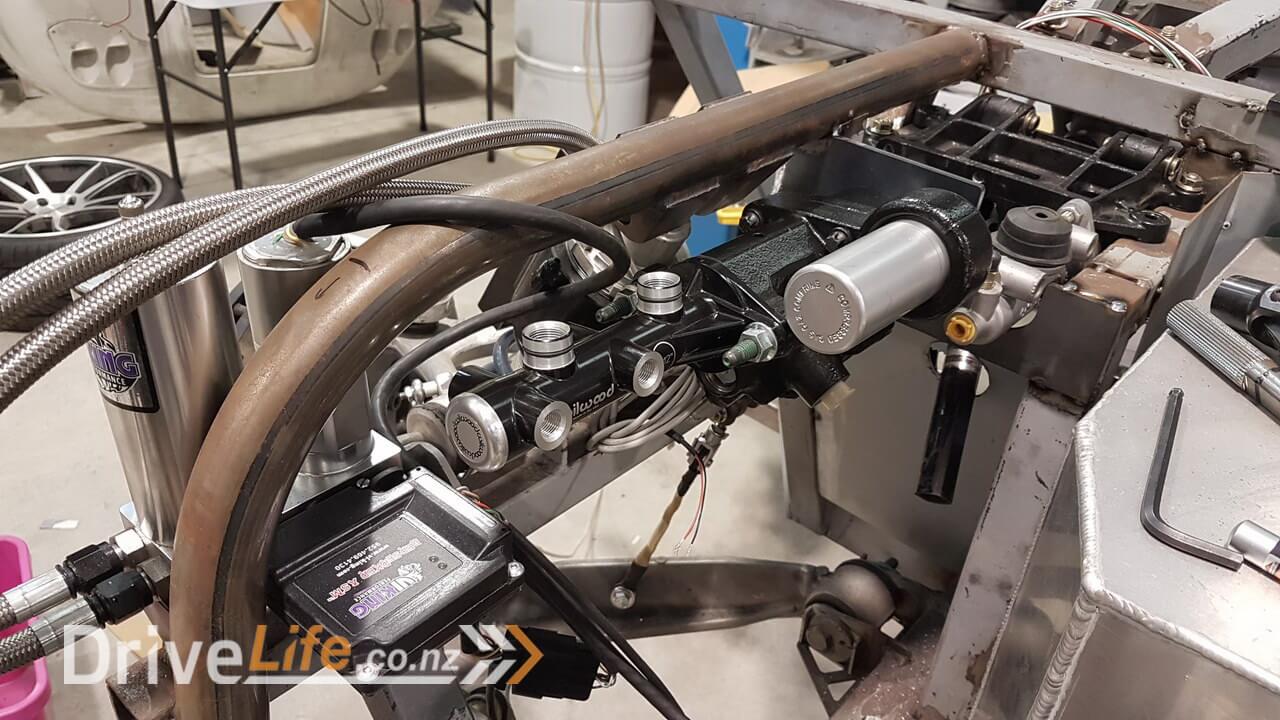
Next I needed to create some more bracing to allow for the large amount of pressure that will come from the pedal being pressed down. It’s amazing to see even 5mm steel move when pressed under heavy brake loads, so I wanted to be proactive about bracing the plate.

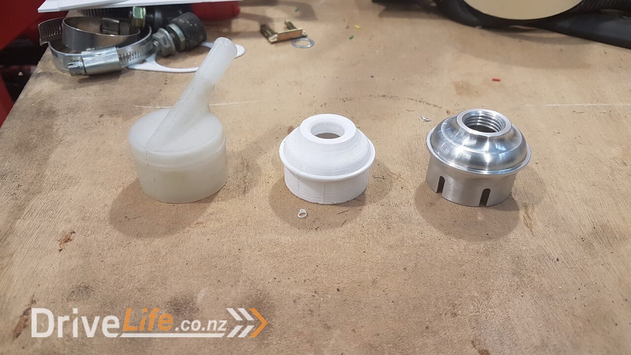
For the moment that was the brake booster mount done. Then I moved onto a special reservoir cap for the clutch master cylinder. Usually the cap for the master cylinder is a cheap looking plastic thing from Willwood, but I wanted something better, but more importantly something that allowed us to use braided hose to match everything else.
I designed something up in Fusion 360 and 3d printed a sample to test. You can see in the photo below the stock plastic item then my 3d printed version and then the final CNC machined unit that Melbar Engineering made for me from my Fusion 360 model.
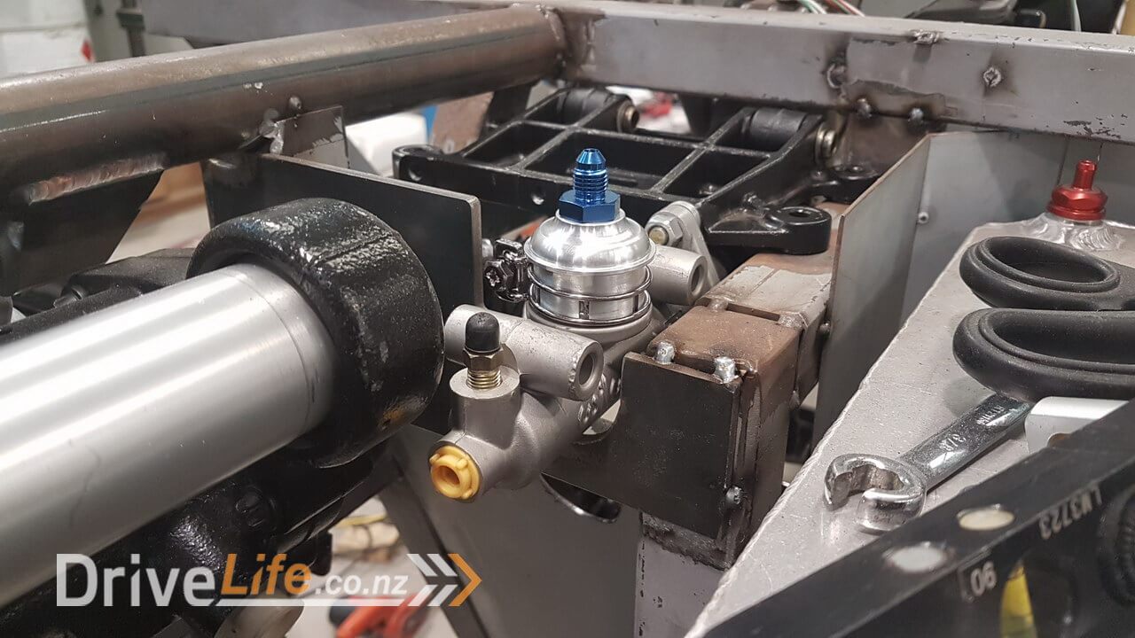
Here’s what it looks like in place.
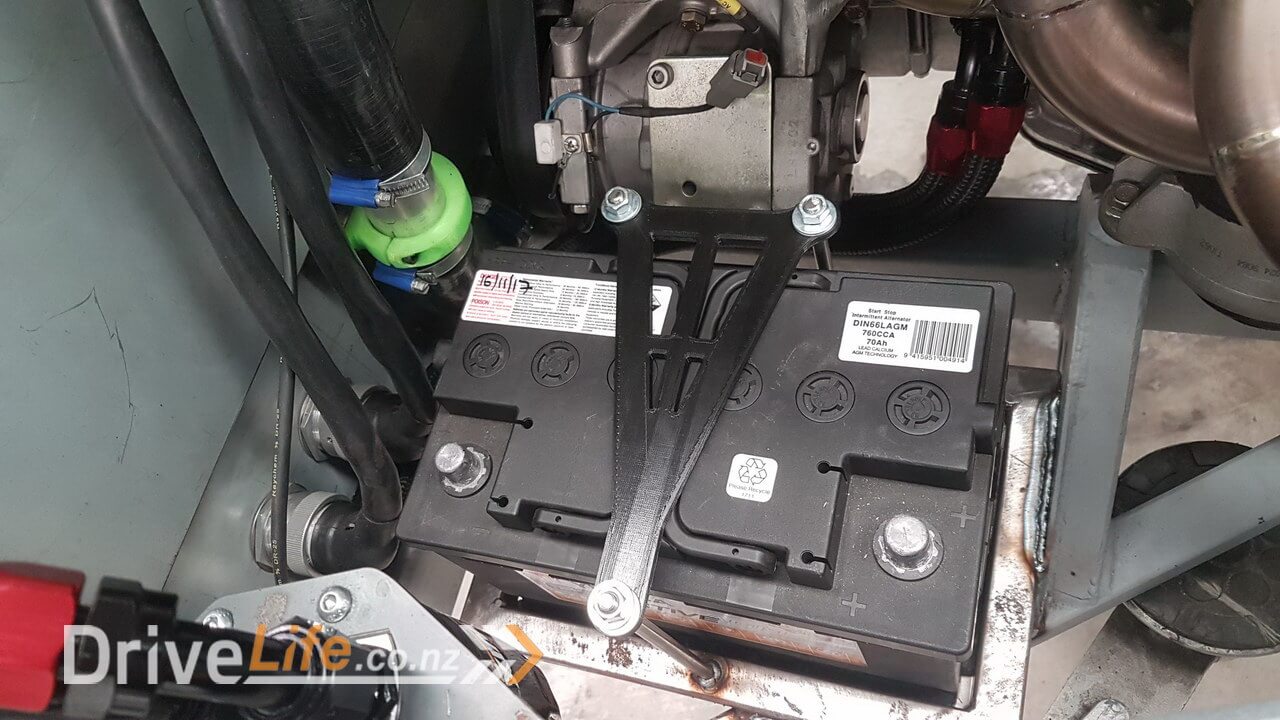
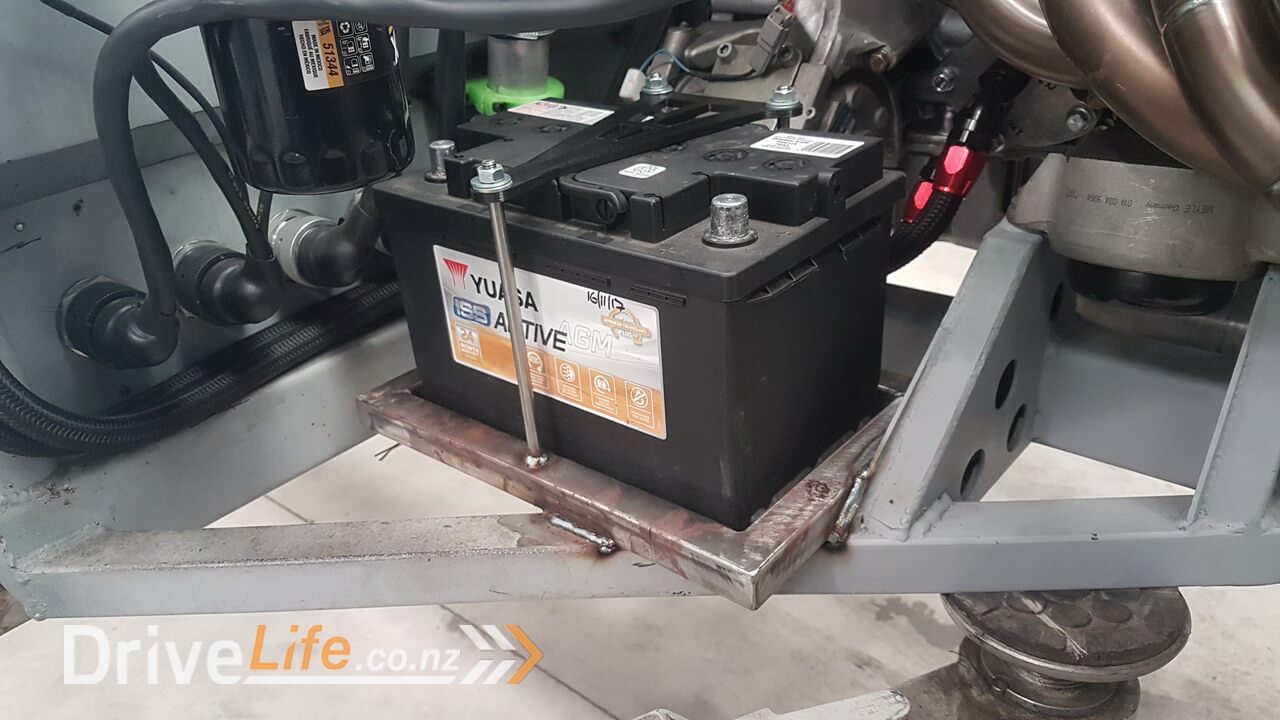
The next episode is going to be all about the accessory pumps like power steering, ride height and ABS etc, but for now I needed to move the battery from its location at the front to the rear. Originally I wanted to keep the battery in the front for weight distribution reasons, however it was taking up what little free space we had at the front so we had to compromise and trade a little more weight in the rear for usable space at the front as I am trying to keep at least a small front trunk / boot space to carry some soft bags etc.
So I started by making a basic battery tray from some square box section and some offcuts from the O.L.S bins ! I am really happy with the result.
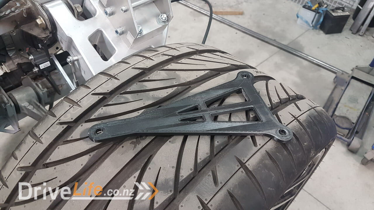
It will need some small braces, but for now it’s very solid. I needed to create a strap to go over the top of the battery and so once again, I started with a 3d print and then had O.L.S laser cut one from 5mm aluminium.
That’s it for now. Things are progressing as you can see and so hopefully life will allow me to keep up the new episodes and we’ll be finished the mechanical side of things soon enough.
Please feel free to comment or ask questions, I really love sharing and discussing our build and cars in general with other readers.
There’s a newer entry in this story, please click here – FZ12 – Part 37
If you’ve missed the last part of our story then click here FZ12 – Part 35
or if you want to go right to the beginning then click here FZ12 – Part 1


Frasier –
Been reading of your project right along.
I’ve been looking at using the engine my self. So, a few quick questions.
What are the make and model of those individual coil pacs you installed on the engine? The v12 M120 from a donor S600 has one integrated that is megabucks to replace.
Also, what make and model is the electronic throttle bodies you put on? The ones from the S600 are fine but, the ones you are using are way more compact.
Thanks in advance for the info.
Dave A.
Hi Dave, The comments come for approval before so it might have seemed like it disappeared but I can see them both here. I did cover the coil packs in an earlier episode, they are from a Honda J series engine. Model code is J32A2, but I am pretty sure that a lot of the J series engine share the same parts. I just happened to have some sitting around for our race car project and tried them to see and they fit perfectly ! Then it was just a matter of getting the plate laser cut and making a couple of small spacers for the bolts and that’s it. I can e-mail you the files for the brackets to hold the coil packs if you like. The throttle bodies are indeed GM ones from a Buick I believe, but again, I think they’re shared across multiple models. Part number is 217-2253. I think from memory they were around $ 170 USD each but that was a few years back. The electrical connectors to wire them in are hard to come by but did find some from a UK motorsport supplier. http://webshop.swindonpowertrain.com/index.php?route=product/product&path=62&product_id=118
Hope that’s helpful 🙂 Thanks for following.
Thanks for the info Fraser.
Do send. I rock ‘old school’ and do most stuff 2d CAD. So, DXF or DWG do me fine.
I love the way you cut off the intake manifold. That gives me ‘ideas'(scary).
Also, I like how you found those SAAB Turbo injectors. The racing ones I see are all massive flow 1000cc or more. Way too short a pulse.
Thanks again. I can’t wait for the Dyno write-up. 550 hp? I’d be happy making 450-500.