


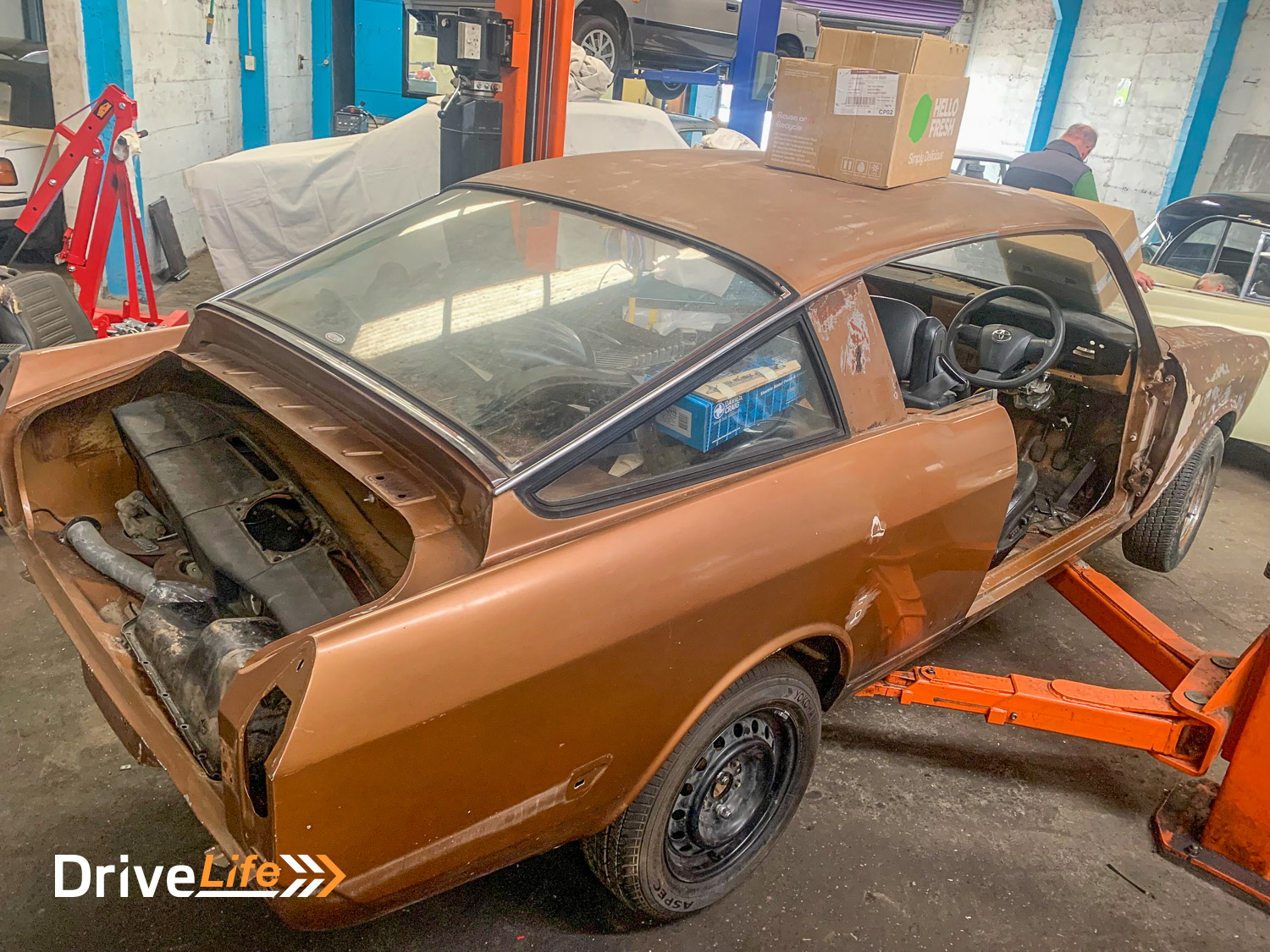
Another weekend, another trip to Hawera to work on the V8 Fastback. This time I’d be taking the top-spec Mazda CX-5 Takami. There are far worse ways to travel 600km.
This weekend would mostly be spent in the engine bay, cleaning up the chassis rails. The British seem to love welding plates onto the chassis rails for different reasons. While only some of these plates would interfere with our new engine mounts, getting rid of them now while the engine isn’t installed makes sense. The result should be a nice, clean lower engine bay. As the project progresses, we’re going to do what we can to remove any clutter, for example, hiding the wiring as much as possible.
Unlike other aspects of this car, those plates are spot welded very well, with some of them welded to one face of the chassis rail, and other ones (like the steering stops) continuing down and under the chassis rail, making them difficult to get at and remove.
On the plus side of things, we did get all of those plates removed and our engine mounts made up. They’re now sitting on the chassis rail and once our LVV certifier has approved them, we’ll get a ticketed welder to weld them to the chassis rail permanently. Those welds will be on the top of the chassis rail as well as on the face, so the strength will be excellent. Like other aspects of this build, once again we are going above and beyond what is required to make sure we have a tight, solid, and safe build.
The rest of this weekend would be spent at another storage location, looking at a Lexus LS400 parts car. Back in Part 3, we removed the rear brake setup from a Toyota Camry parts car, aiming to adapt the brakes and hubs to fit our Toyota Hilux diff. But, since the Hilux is rear-wheel drive and the Camry is front-wheel drive, the difference in sizes between the hubs is too much for us to do much about without lots of modifying. So our new plan is to look at the rear of the LS400 and since that car is rear-wheel drive, check if we think those rear brakes will fit better, we can remove them and get stuck into modifying them (if needed) to suit the Hilux diff.
If we do go to LS400 rear brakes, we’ll likely look at using the entire front brake setup from the LS400 as well. Keeping the front and rear brakes from the same model is a good target to aim for.
While working in the engine bay, the final decision was made around the battery location; we’re moving it to the boot. This will give us a better balance in the car, but it also frees up the engine bay for a remote brake booster with dual-master cylinders. We absolutely want to go to a dual brake master for better and safer braking performance, but there isn’t room for all this immediately behind the pedal box. So instead, we’ll replicate the remote booster system such as used in a 3-Series BMW, where there is a rod from the pedal box that activates the booster. We’ll use a slimline booster to keep it away from the heads, although there should be plenty of room for the setup regardless.
The Sunbeam Rapier Fastback has an enormous boot (538 litres!), so there’s ample room in there for the battery, and we’ll hide it behind a panel. Since we’ve moving the fuse box from the right side of the engine bay to the left side of the cabin, we may take the opportunity to move the battery to the left side of the car as well, so it can feed straight through to the new fuse box on the same side of the car.
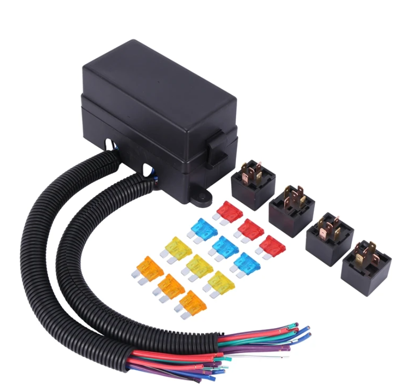
We’ve purchased a new fuse box, complete with 6 relays. The original fuse box had a grand total of 4 fuses, but that’s not going to cut it for us with all the electrical improvements we’re planning. The new fuse box carries 15 fuses, and we can use the relays for the power windows, headlights and other items that have a heavy draw and need a relay. We’re going to mount the new fuse box under the parcel shelf in the passenger’s footwell, and if we run short of fuses or relays there’s enough room there for a second one.
Project V8 Sunbeam Rapier Fastback: Doors, Windows
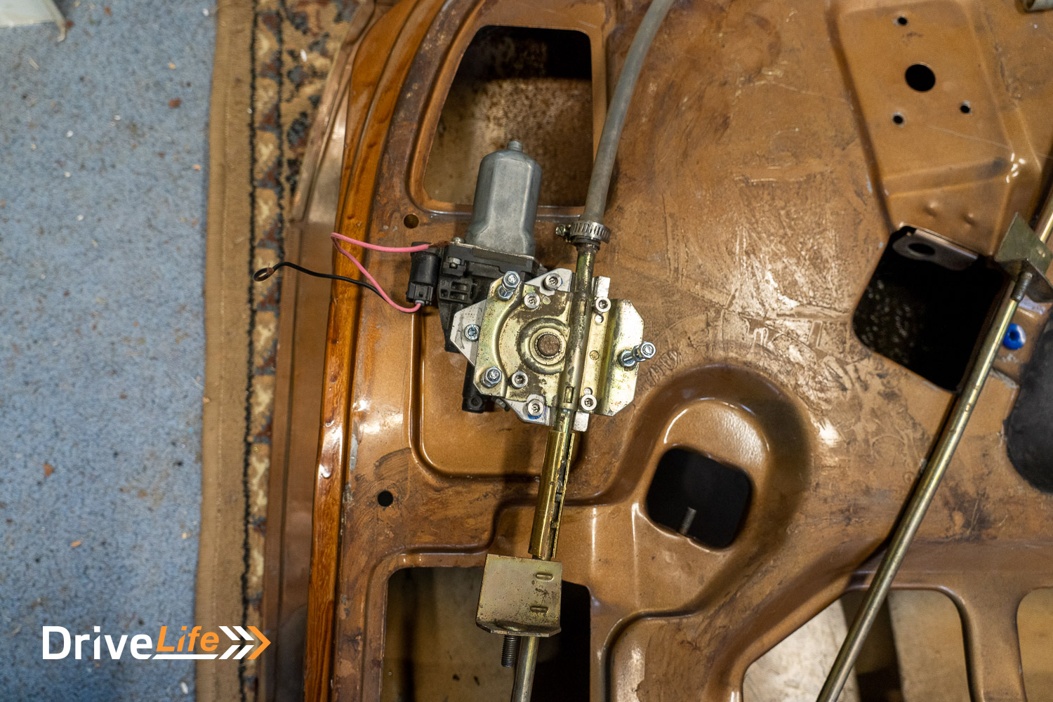
Since our project car is 300km from home, I’ve got the doors with me at home so I can get work done on them while not in Hawera. You would have already seen our article on the power window conversion; this has moved forward nicely, with our friendly engineer designing and building alloy base plates for the Toyota power window motors to sit on. This base plate is then bolted together with the Sunbeam window winder mechanism, so the whole thing is one, tight unit. This means no play between the two components and that should mean reliability.
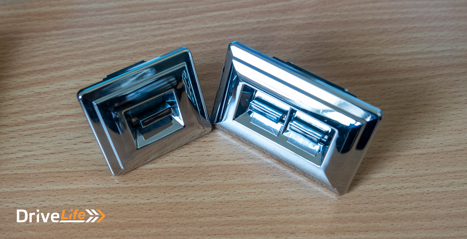
Our new power window switches turned up, and have been stored until we’re ready to use them. We’ve gone with switches that replicate early HT Holden Premier power window switches. Why? An HT Holden Premier was the first car I ever saw with power windows – that was something special in the 1970s – and the look of them is retro, fitting in with the 1973 model year of our project car. I’m hoping they end up looking like they were installed at the Rootes Group factory.
We’ve tested the power window motor in the doors and it works perfectly, without the glass at least. That can all be put aside for now, and once the other work on the door internal is complete, they can go back in permanently.
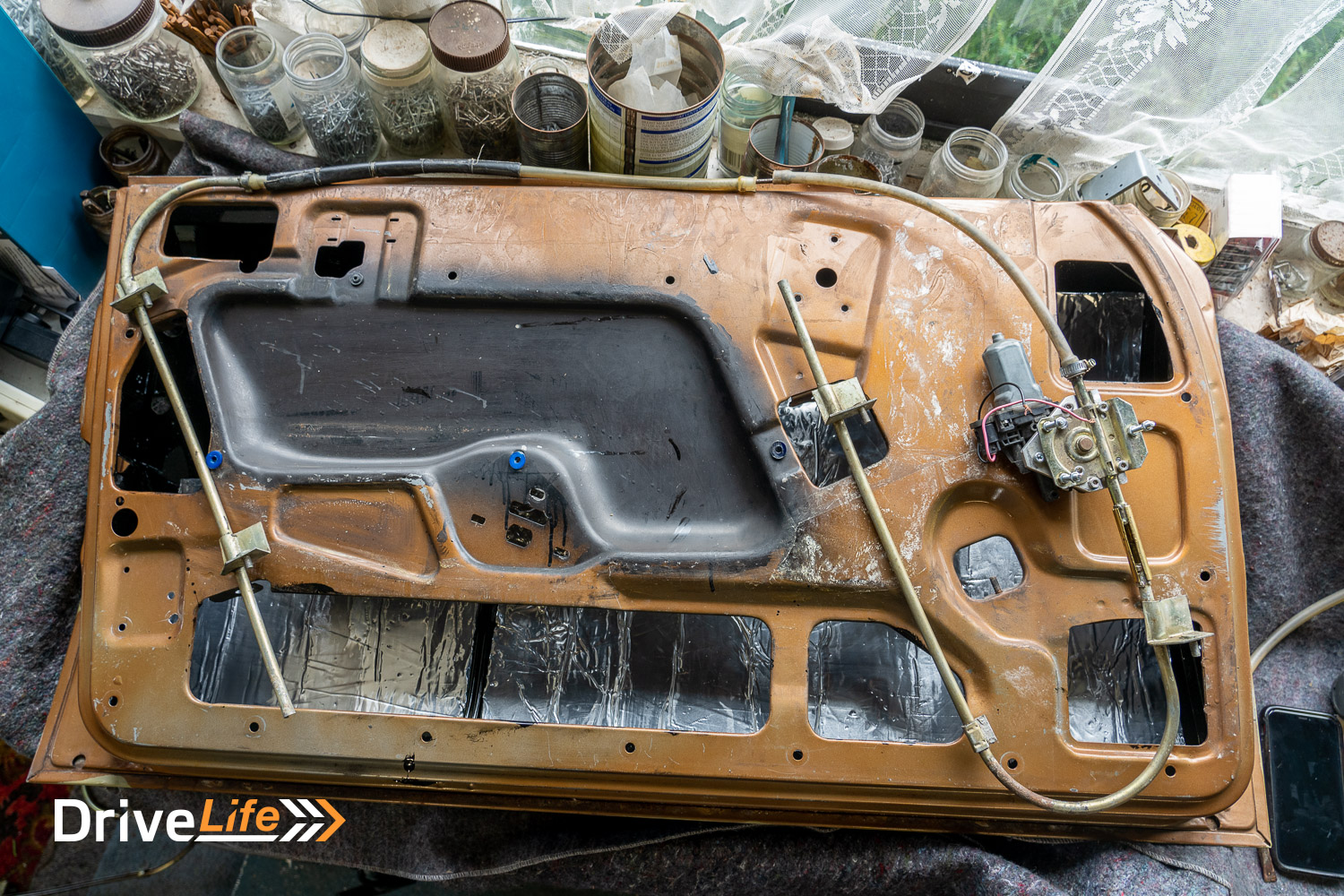
That other work includes installing the solenoid for our door poppers (already covered in Part 5), putting POR-15 rust neutraliser inside the doors, installing sound deadening, and making up new door cards.
Before any of this, the doors went off to The Surgery to have two-pot epoxy applied to the outside skin. The doors were prepped first and then the two-pot epoxy was applied. That epoxy means the outsides of our doors are now totally protected against any future surface rust.
We purchased some POR-15 products for the inside of the doors; Steel Cleaner, Metal Prep, and POR-15 Rust Neutraliser. This three-step process will do the same as the epoxy for the inside of the doors; it should stop future surface rust. Once we had done the POR-15 process, we applied some sound deadening to the inside of the doors to help cut down on road noise coming into the cabin. We’ll do this where ever we can, inside panels etc.
While our existing door cards are usable, I want to make some new ones since we are dropping the window winder handle. Making new ones out of plastic means that if the door cards get any moisture or water on them, it doesn’t matter. Old british cars are known for having warped door cards. We purchased the plastic door card from a local upholsterer, Rotary Trimmers, and will use the old cards as a template.
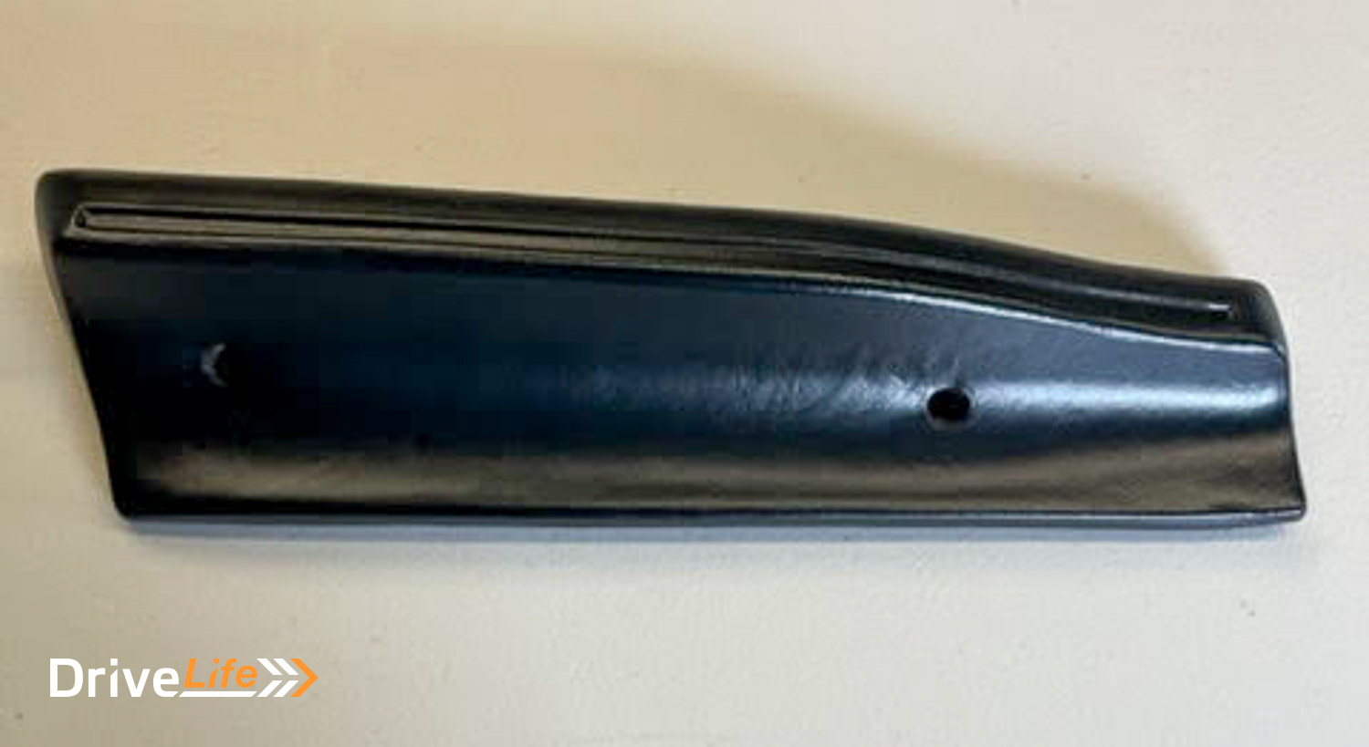
In between all this, our 4 armrests were picked up by Fibrenew. They specialise in restoring old armrests and the like and brought our armrests back to life. While our armrests had no dents or rips, the vinyl had worn through in a number of places. Fibrenew rejuvenated them, and we have them sitting aside, waiting to be screwed back on.
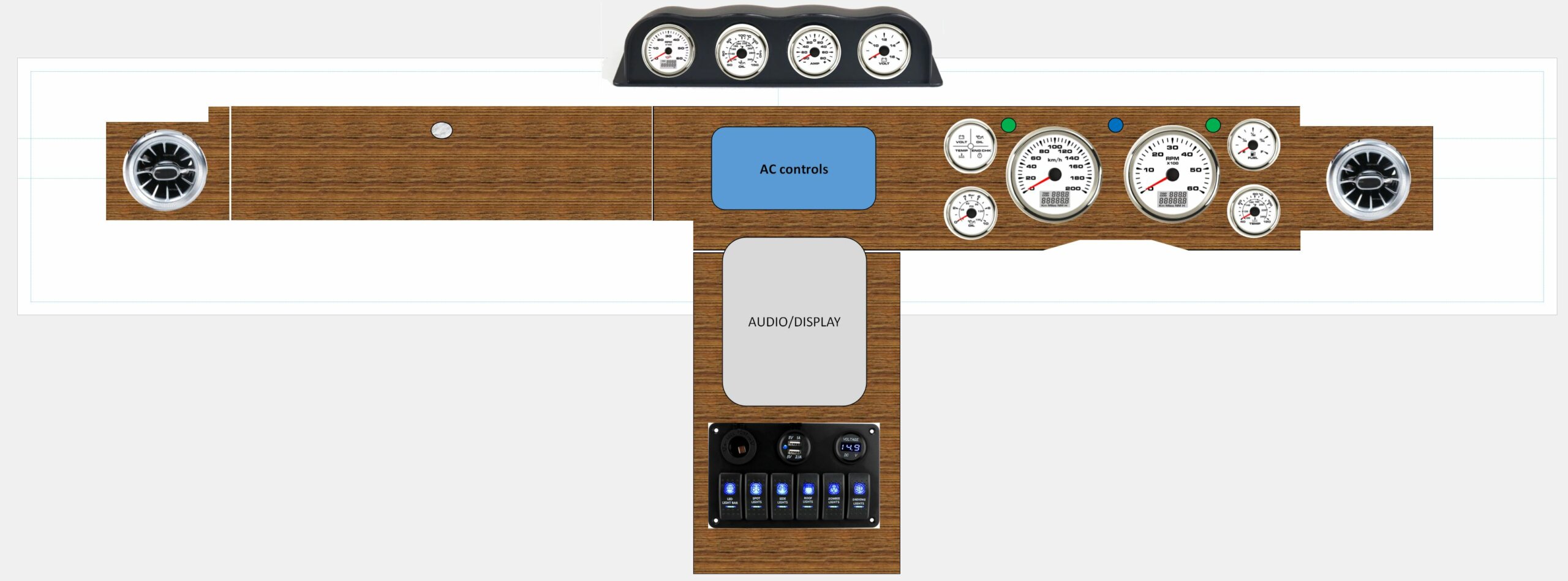
Project V8 Sunbeam Rapier Fastback: Dash & Console
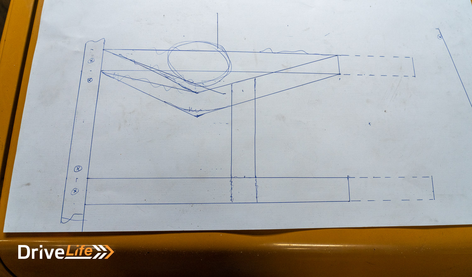
In the last article of this series, we discussed the new dashboard for our project car. We want to remove the vinyl-covered one and install a wooden dash from a Humber Sceptre. But we’ll only use the Sceptre dash as a template, as we have our own design of how we want the new dash to look:
We can’t actually do the new dash until we have the Toyota electric power steering completely installed, as it will impact the way the lower part of the dashboard looks and fits.
Regardless, we can still do other things for the dashboard. One of those things was looking at how we want the wood veneer to look. We’re definitely aiming for a burled walnut finish, but that doesn’t mean we need to use burled walnut veneer. We can use another veneer and make it look like burled walnut.
A friend who makes surfboards has a load of veneers he imported from the USA, and we can pick and choose the pieces we want from that selection and get it stained to look how we want it, and then epoxy it onto the dashboard.
But it’s not just the dash we are talking about here; we’re going to design a new centre console, then another piece of veneer-covered ply will go up to join the dashboard. We’re also tossing around the idea of having wood-capped doors; very 1970s and may well just fit in with the look we are going for. But that may be a step too far.
Project V8 Sunbeam Rapier Fastback: Steering, Seats & Chassis
Another weekend trip to Hawera, this time in the Kia EV6 GT Line. The EV6 would be the first EV I had driven to Hawera, to make it on one charge (and I had 113 km of range left over).
This weekend would be focused on getting the electric power steering (EPAS) mount measured up and designed.
While the electric power steering is already bolted to the lower dashboard, it’s not enough. After lots of discussions, we are intending to go with a triangle-type of bracketry, to give maximum strength. This will be a mix of box section steel, angle, and flat steel, and it will be tied to existing bolts on the firewall where possible. Once we had the desired design, it’s a matter of sending our design to our LVV Certifier to get him to (hopefully) give us the go-ahead to proceed, or he may suggest more changes to the design.
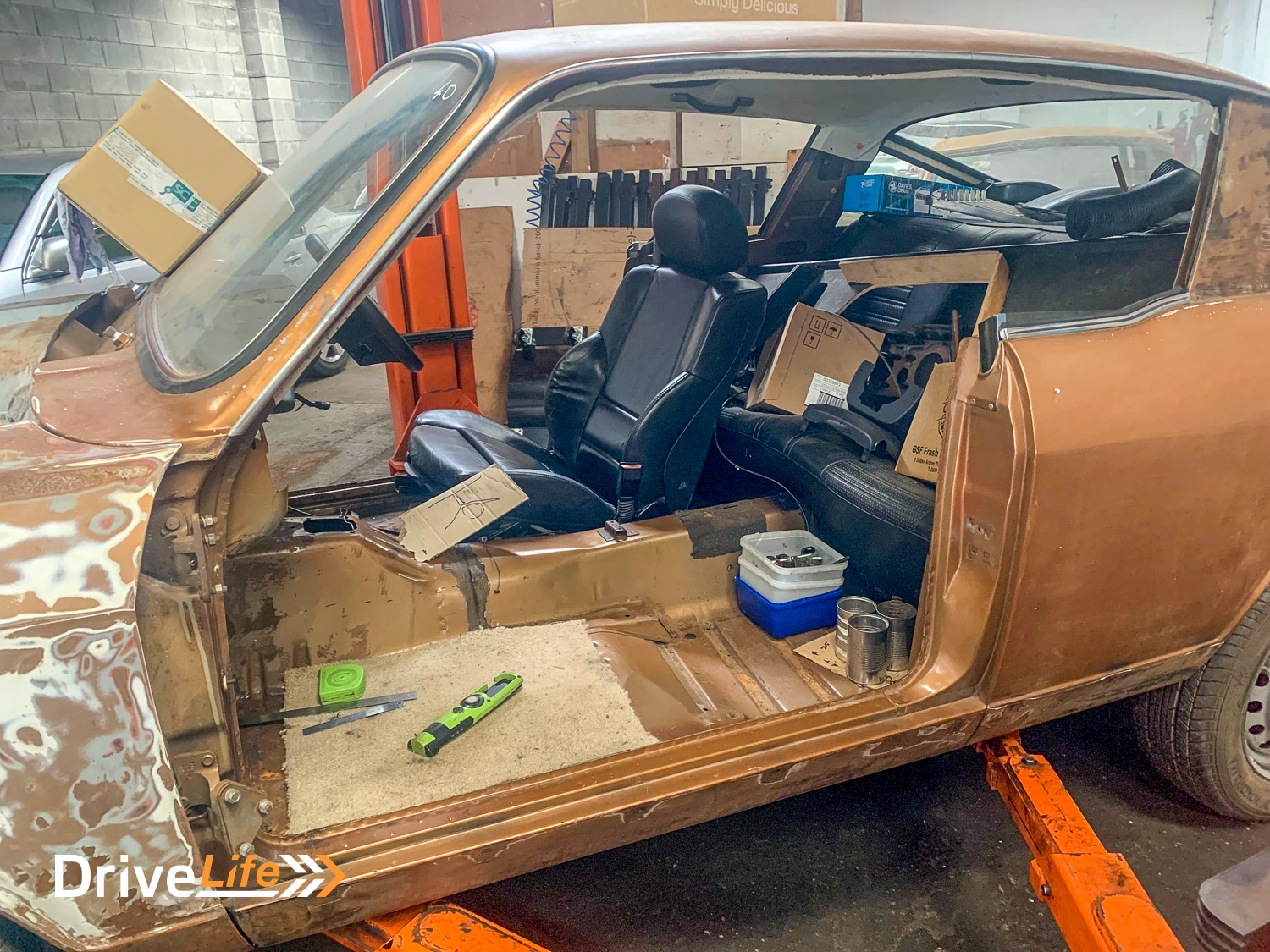
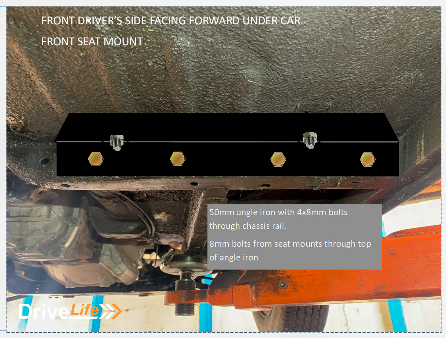
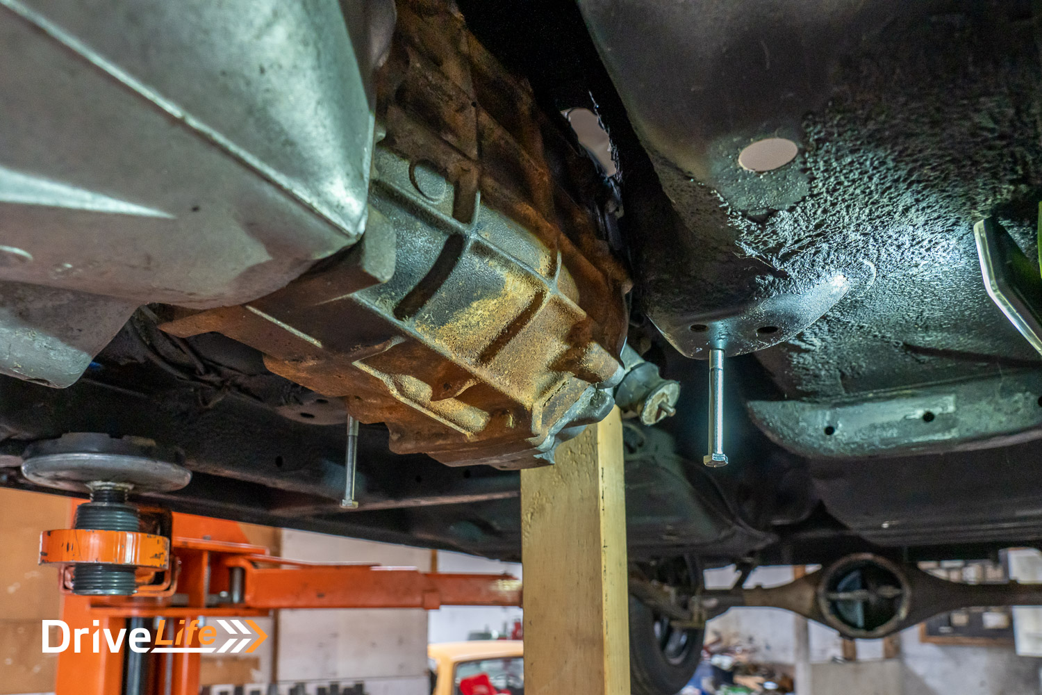
We’ve also planned out (in principle) the seat mounts. Back in Part 2, we bought some BMW E46 M3 electric seats for the front of the V8 Fastback. The main reason for the seat change is to get rid of the car’s existing flappy seatbelts. They’re terrible. The M3 seats have built-in seatbelts, making them much tidier and easier to use.
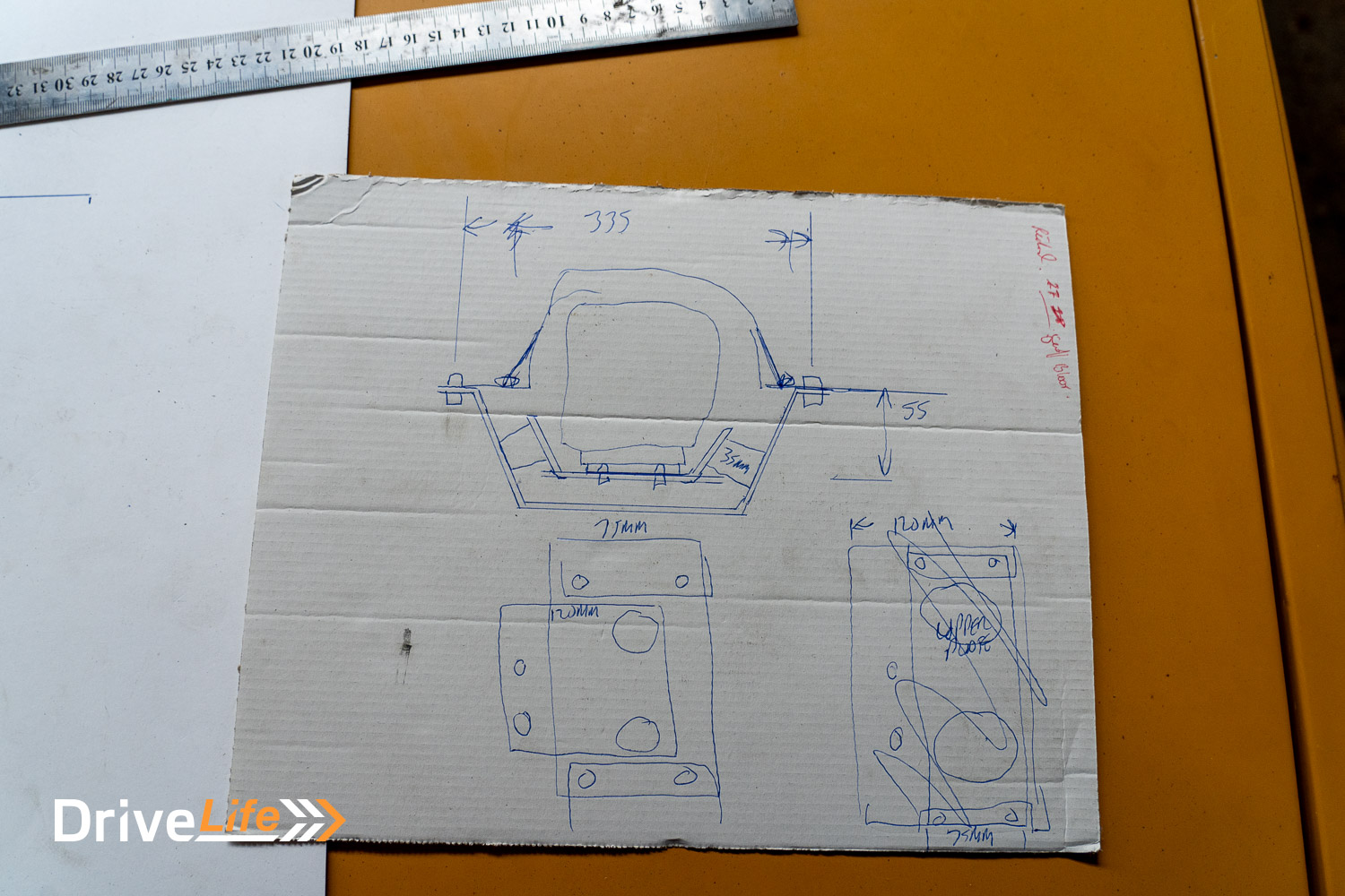
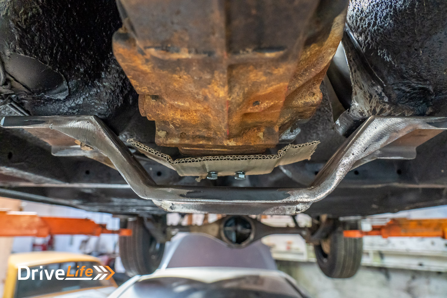
But of course, these seats require a lot of bracing. LVVTA calls them ‘Fully Stressed Seats” because they have built-in seatbelts. We’re looking at a design using a plate against the transmission tunnel that will join onto a (new) flat steel plate across the floor pan, to another plate that will be bolted to the sill. That’s at the rear of the seat. At the front, we’ll do a mounting system under the floor that will connect directly to the chassis cross-member. LVVTA has lots of information about sizes of steel and types of bolts etc required for all seats, so we’ll be following this to give us guidelines on what we need to do to get certification.
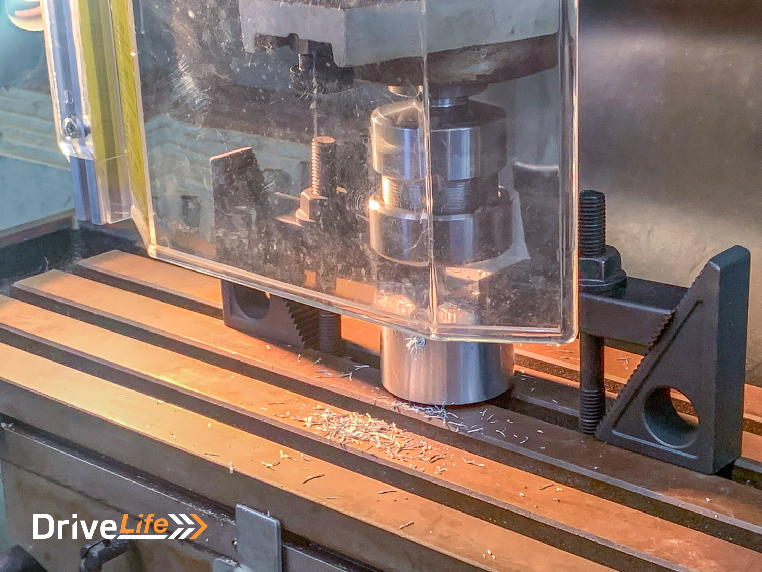
Another job this weekend was to get more done on the cross-member spacers. Since our Triumph TR7 cross-member is lower at the front than the back, we have a gap of around 50mm that needs to be taken care of. We’ve already had some solid alloy spacers made up for this task, but they won’t go straight in, as the inner guard comes down the side of the chassis rail and past it about 10mm. To make the most of the strength of this design, we marked lines on the spacers and sent these off to get grooves cut into the tops of them. Once in place, the inner guard will sit nicely inside the new groove. Then, we’ll drill a hole up from underneath the cross member, right through the alloy spacer, and then through the chassis rail. We’ll insert a crush tube inside the chassis rail and then put a single bolt all the way through it all. Not having done this yet is holding up further progress on things like the gearbox mount, so we need to get it sorted.
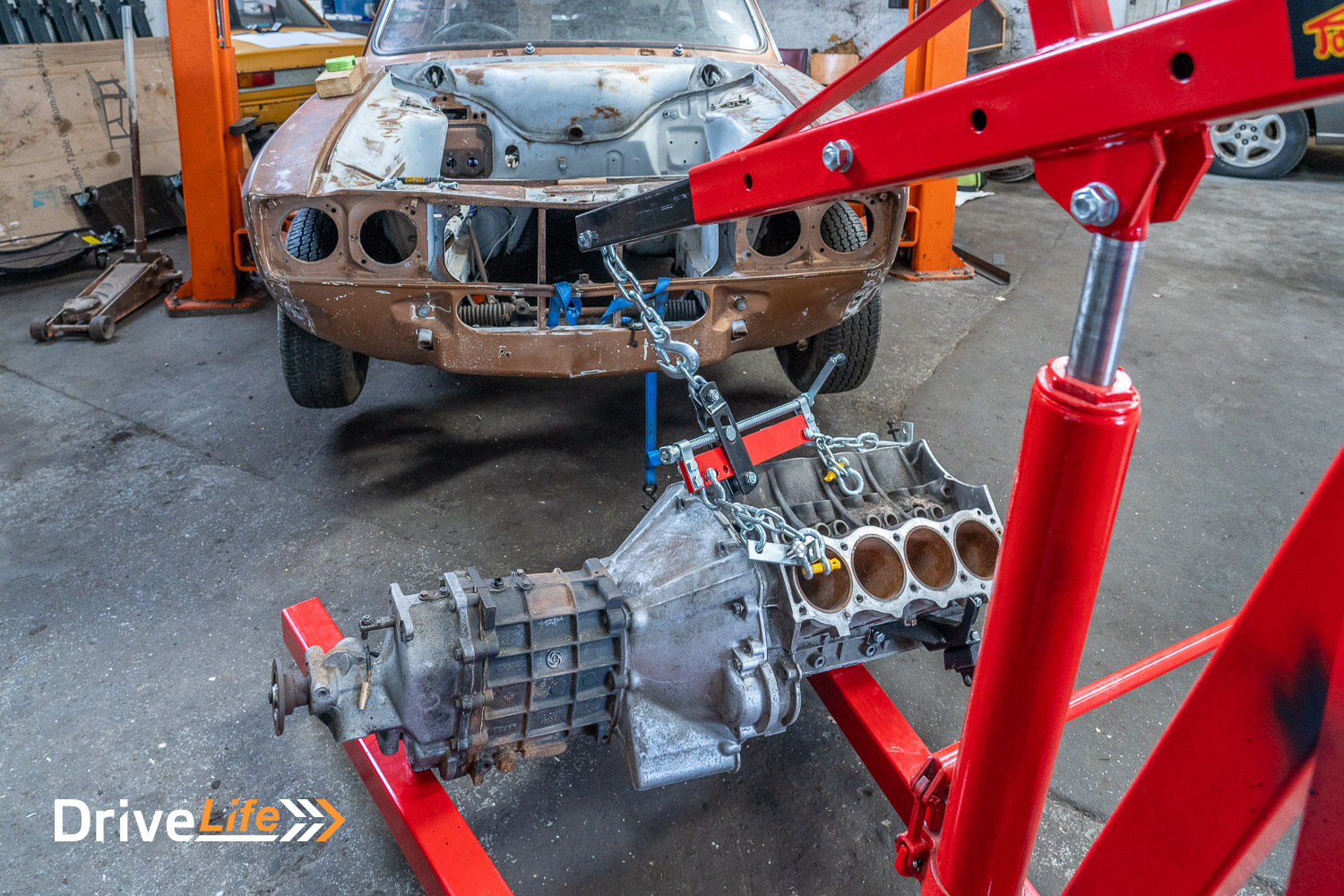
While under the car, it was worth checking out the gearbox mount, or what we should do with one. Our Rover gearbox didn’t come with the mount, but from memory, a standard Rover gearbox mount should be very usable. We’re hoping it will go right across the chassis rails, making it almost simple to bolt the gearbox mount onto. We’ve sourced a used gearbox mount and will look at this more the next time I’m up.
Project V8 Sunbeam Rapier Fastback: Gearbox Mount
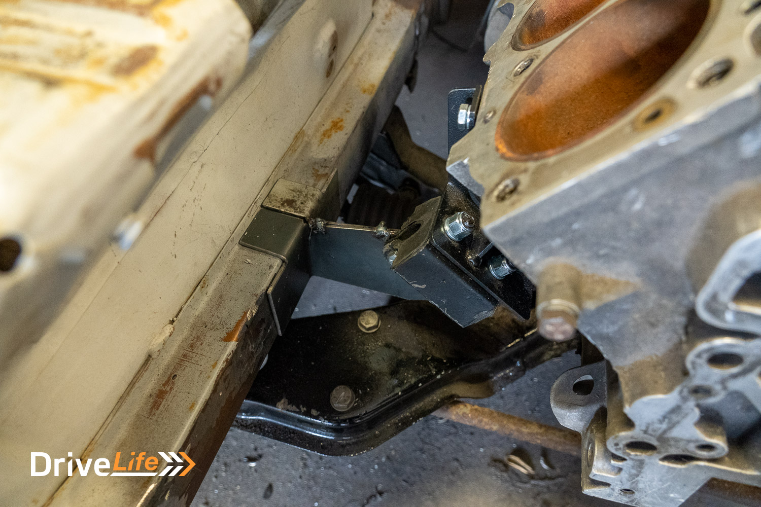
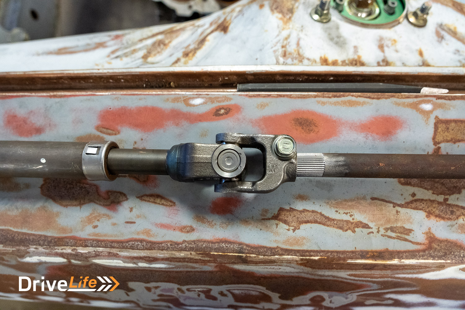
My next weekend in Hawera would pretty much be spent designing the gearbox mount. The reason for it taking so long is its importance; the mount will determine the height of the gearbox, as well as the location of the engine and gearbox in the car. Getting this wrong now would be a major issue later on.
On the plus side of things, once that mount is in, it means we can install the diff head and get the driveshaft organised. Having a gearbox mount is going to be a milestone for our project car.
Previously when considering how the gearbox mount would look and fit, we bolted the original Rover V8 mount to the gearbox and would design some steel plates to run north-south under the car, and bolt the mount to those. But once we jacked the gearbox up to its correct height, that idea was thrown out the window.
Plans changed when the gearbox was lifted to line the gearbox with the diff; all of a sudden, our plans to use the original mount would not work. So it was Plan B into action – we would use the original Sunbeam mount holes, and make up two plates to bolt to them. One plate would bolt to some existing spare holes under the gearbox, and then we’ll add two cotton-reel rubber mounts that are bolted to a lower mount. That lower mount will bolt to the original bolt holes on the floorpan.
To make sure we are making everything as strong as possible, we replicated the angles of the original Rover gearbox mount. There was lots of measuring going on, double and triple-checking.
We took ideas and measurements and made up initial drawings, and then final drawings. We’ll need to get this all certified of course but are confident this is well beyond what is required. The drawings were picked up by an engineer, and the mount was made the following week.
The mount now made, next trip up we’ll get it bolted in place, and then can start putting the diff head in and organising the driveshaft.
After working on the mount, it was time to get our newly machined spacers in place. These will take up the space between the original Triumph TR7 front crossmember and the chassis rails. We had some slots machined into the top of the spacers so that the part of the inner guard that comes down below the top of the chassis rail will fit into the slots. Next up was drilling the holes up through the bottom of the spacers right through the chassis rails. Then we drilled larger holes down from the top, and inserted some crush tubes and later will be tacking them in place, and then bolting it all together. Other than getting it certified, replacing all the rubber bushes and painting components, that’s the front end of the car done.
Project V8 Sunbeam Rapier Fastback: Electric Power Steering Mount
Yet another weekend away to work on our car had two main aims; get the gearbox mount in and the power steering mount designed.
With a bit of tweaking, we did get our new gearbox mount in place and are happy with the design. It’s extremely solid and high enough to not cause any issues on the road.
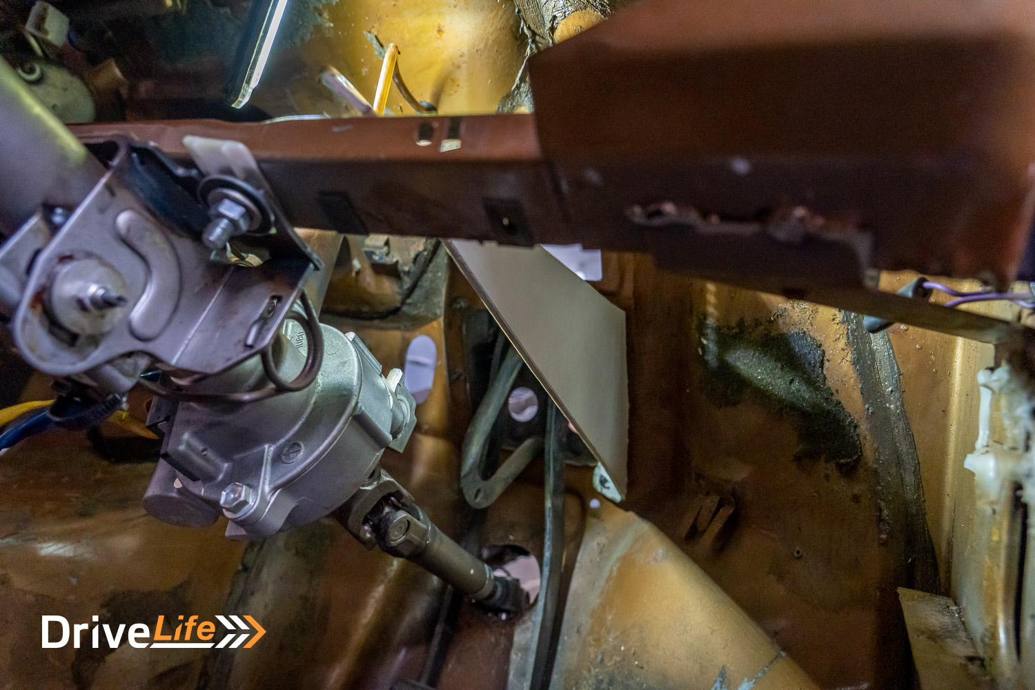
While we had grand designs for our original electric power steering mount, a rethink of this means we would have something simpler, and stronger. So after lots more talking, we decided on two triangular brackets that will bolt to the pedal box, and from there come up to the bottom of the dashboard. We’ll insert a solid piece of steel in the dashboard channel for strength, and then bold each bracket to that. Between the brackets, we’ll weld a plate and from the centre of that plate we’ll have a drop-bracket that will go down to the power steering motor mount.
That’s just one paragraph but with so much measuring and double-checking, it was an entire weekend’s work to get this right. We’ve now created thick cardboard templates of our triangular mounts and will send these off to get made out of 3mm steel.
That’s it for the moment. Next time we’ll hopefully be installing our two brackets and then designing the centre bracket. We can also move on to the rear brakes, and perhaps install the diff head and get a driveshaft made up to suit.
There is still so much to do, but every step forward is progress.
Join our mailing list so you don’t miss another article in this series.
Read Part 1 of this series here
Read Part 5 of this series here
Read Part 7 of this series here


Great project. Looks like you are having a lot of fun there. All the best for a satisfying result.