


Well, in what seems like an endless process, today we’re going to continue looking at the main wiring looms for our FZ12 project.
I have to admit, this part of the project really surprised me about just how long it would take and how much was involved. I guess in the past my car projects have either been production car modifications or in the case of our NSX race car, we started the wiring from scratch, but I didn’t do a lot of the wiring so didn’t really have a good appreciation for just how much was involved.
My friend Lance agreed to help since he had more experience with building wiring looms with the specifications we wanted to use. For those who haven’t read you can read about the first part of the wiring build here first. FZ12 Wiring – Part 1
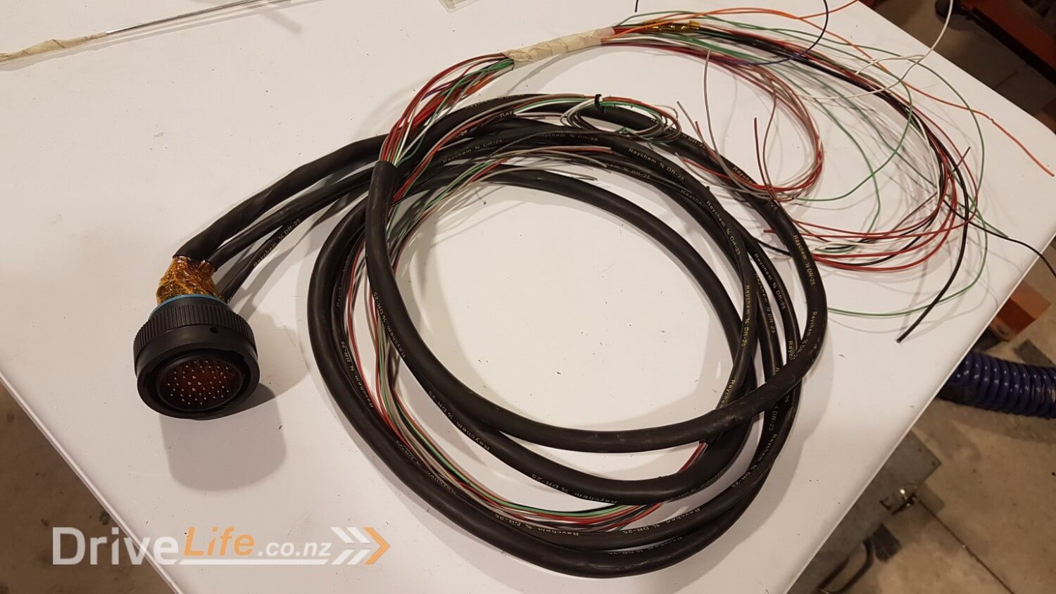
At the end of the last episode we had only completed what are called the bulkhead ends of the engine loom. They are a waterproof sealed connector that attaches to the rear firewall / bulkhead of the FZ12 and that allows the wiring to be passed through into the cabin to be wired into the ECU and PDM.
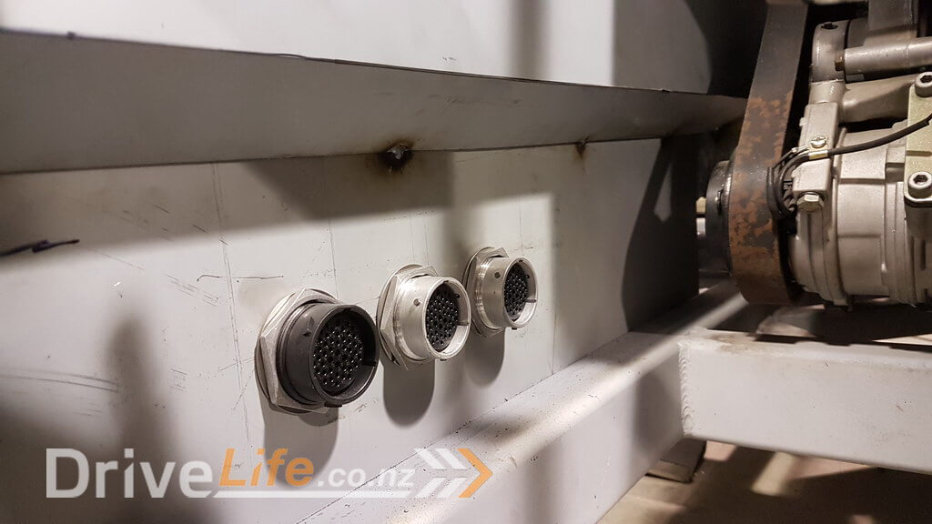
These bulkhead connectors were split into left and right bank of the engine since there was so many wires on each side. In total we expected to only need 2 bulkhead connectors originally, each with 47 pins each, but due to the amount of extra sensors and devices on this car we needed to add a third and then a fourth bulkhead connector to the rear. We had spent quite a few days sitting down walking through all of the options, sensors, lights, switches etc that we could think of, however there was plenty we missed so it’s been a bit of a moving target to some degree, but Lance’s experience meant that he allowed for those mistakes or changes and so we were able to adjust fairly easily.
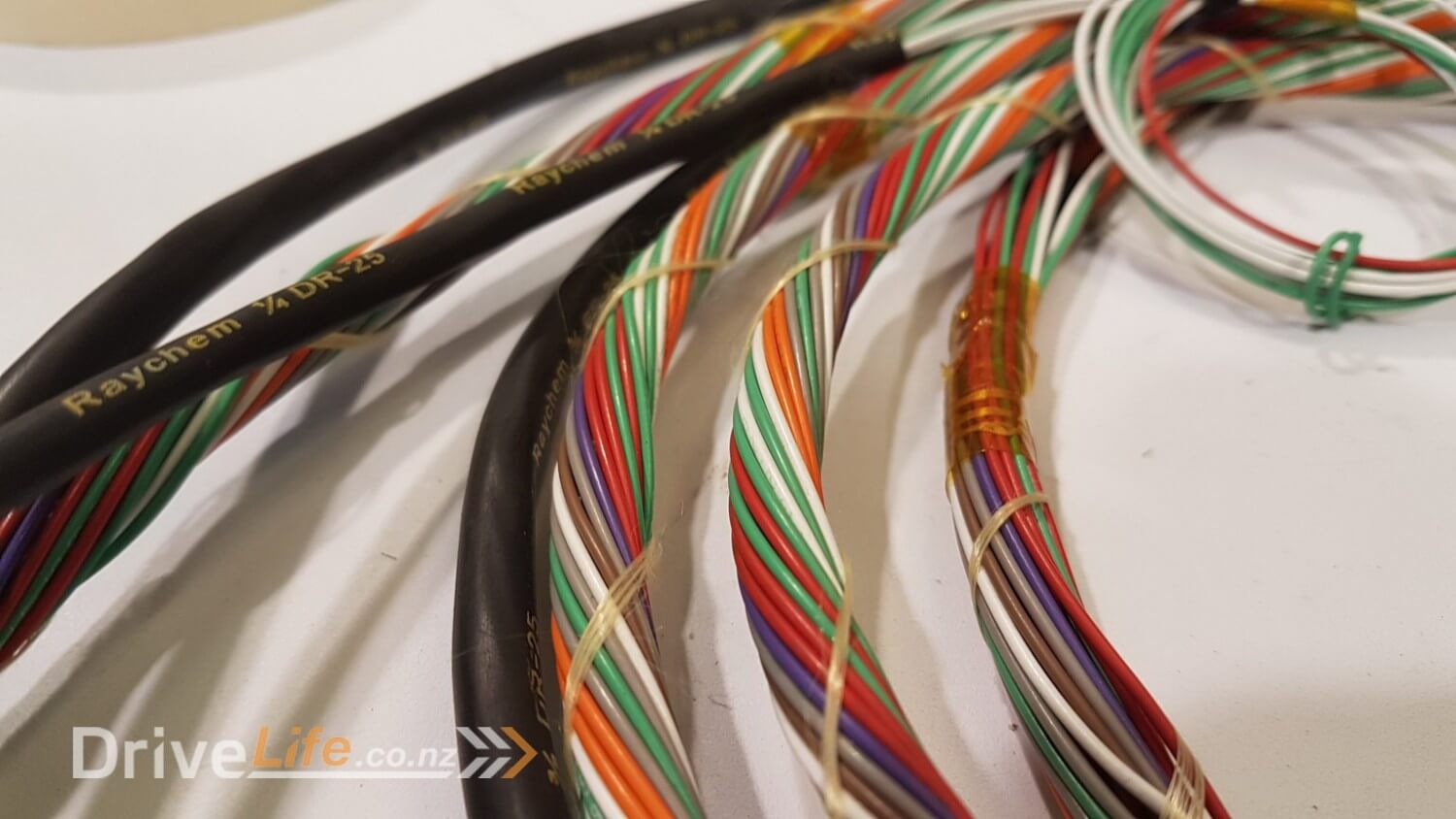
So here we are with the other end of the main engine loom still to finish and apply connectors.
One of the terms I’ve used in this build so far is “V12 tax”. What I mean by that is that in a normal engine you only usually have 4 or 6 cylinders to worry about, not 12. Accordingly that translates to more, lots more of everything including wiring and connectors !
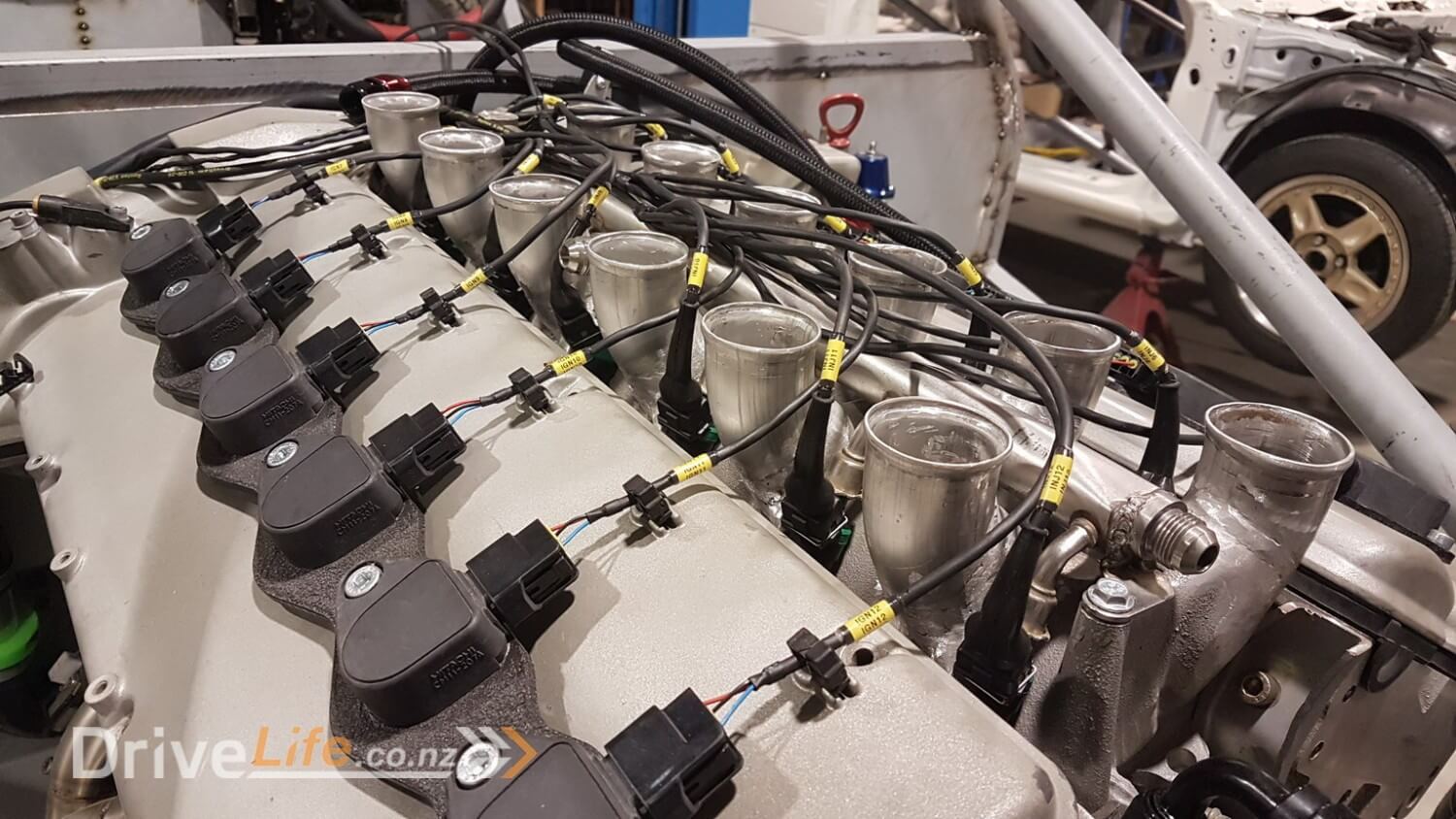
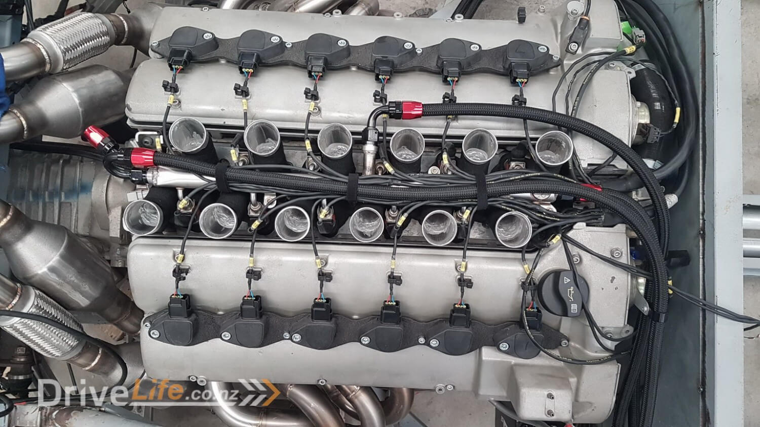
2 wires for each injector and 3 wires for each of the Honda coils we fitted some time back.
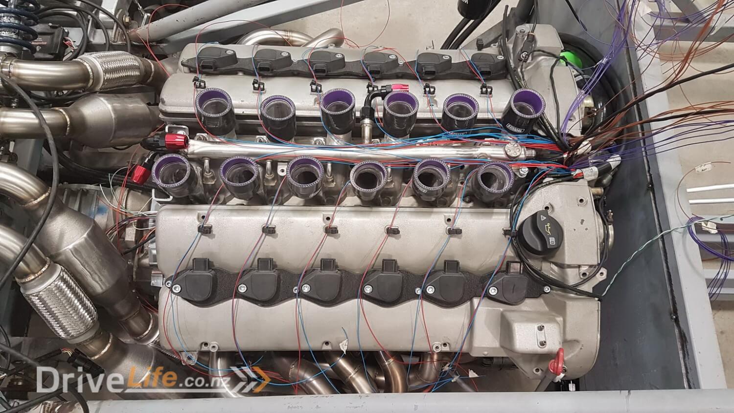
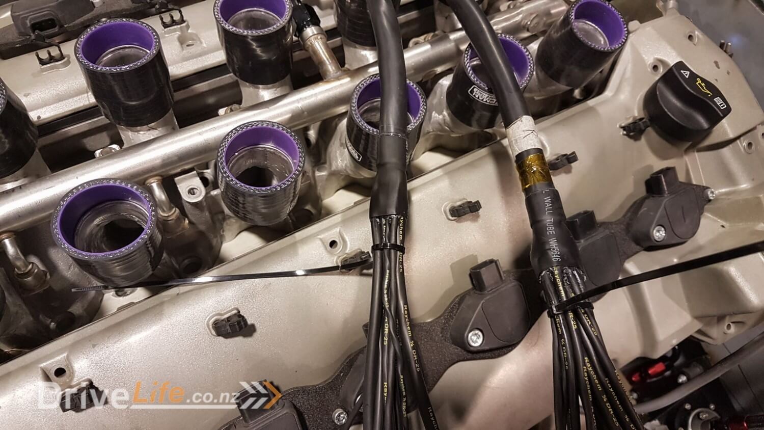
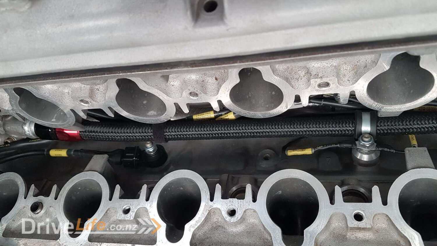
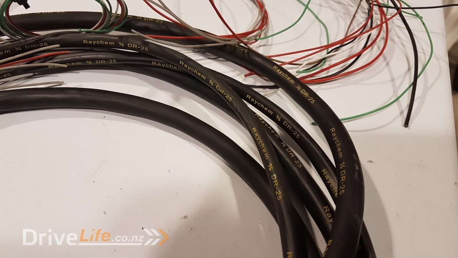
A very important part of the entire loom is to make sure water and other contaminants don’t get into the connectors. That is why you will notice that on every area of the loom there is sealed heatshrink or a rubber sealed connector such as these for the ignition coils.
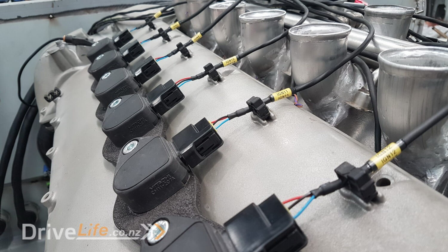
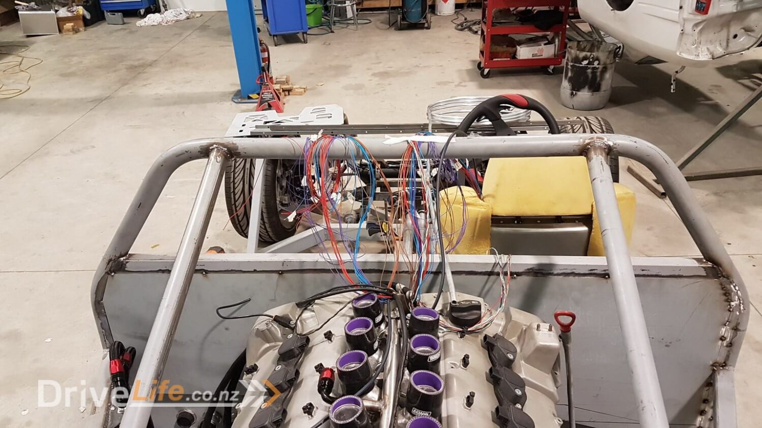
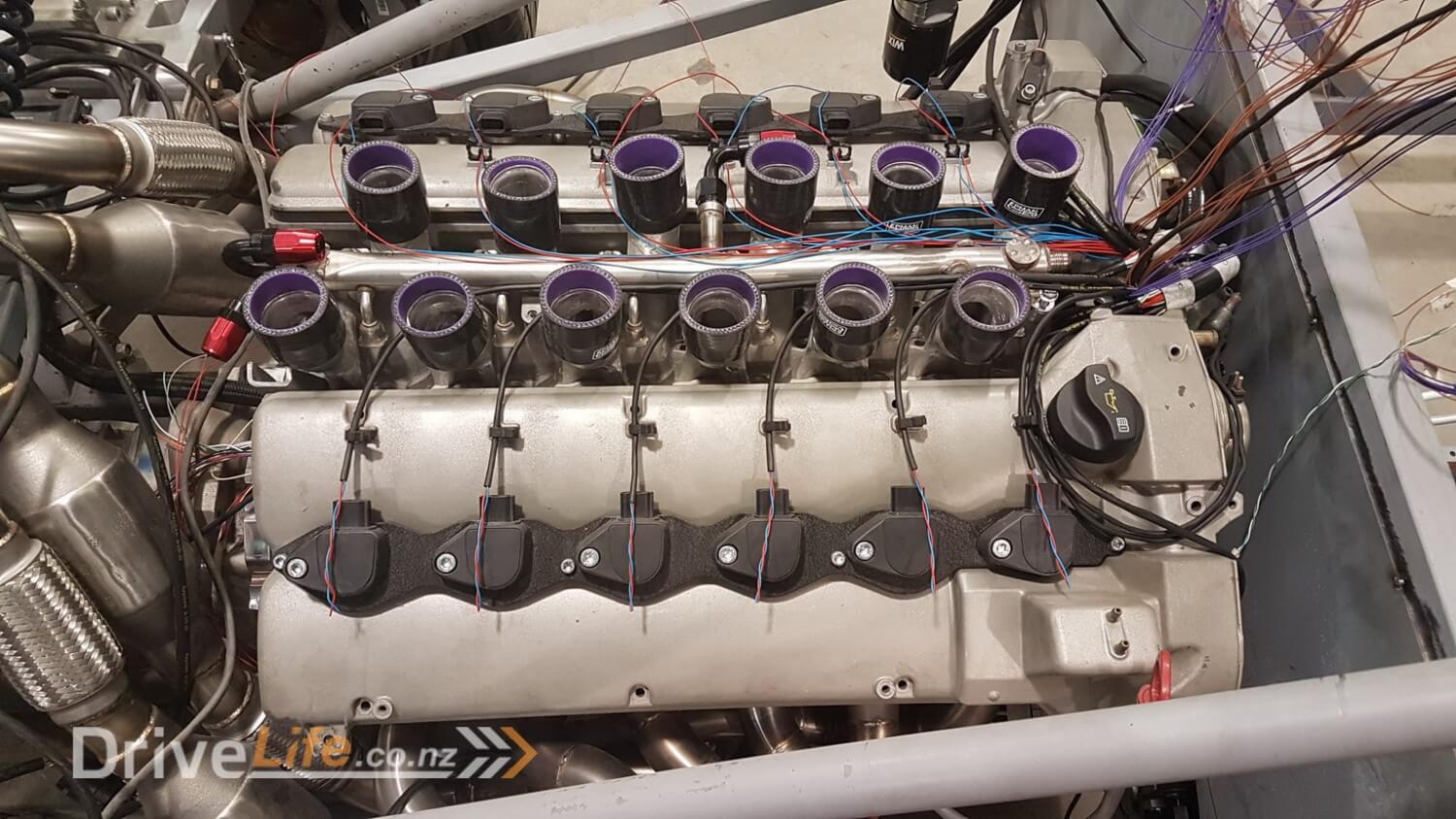
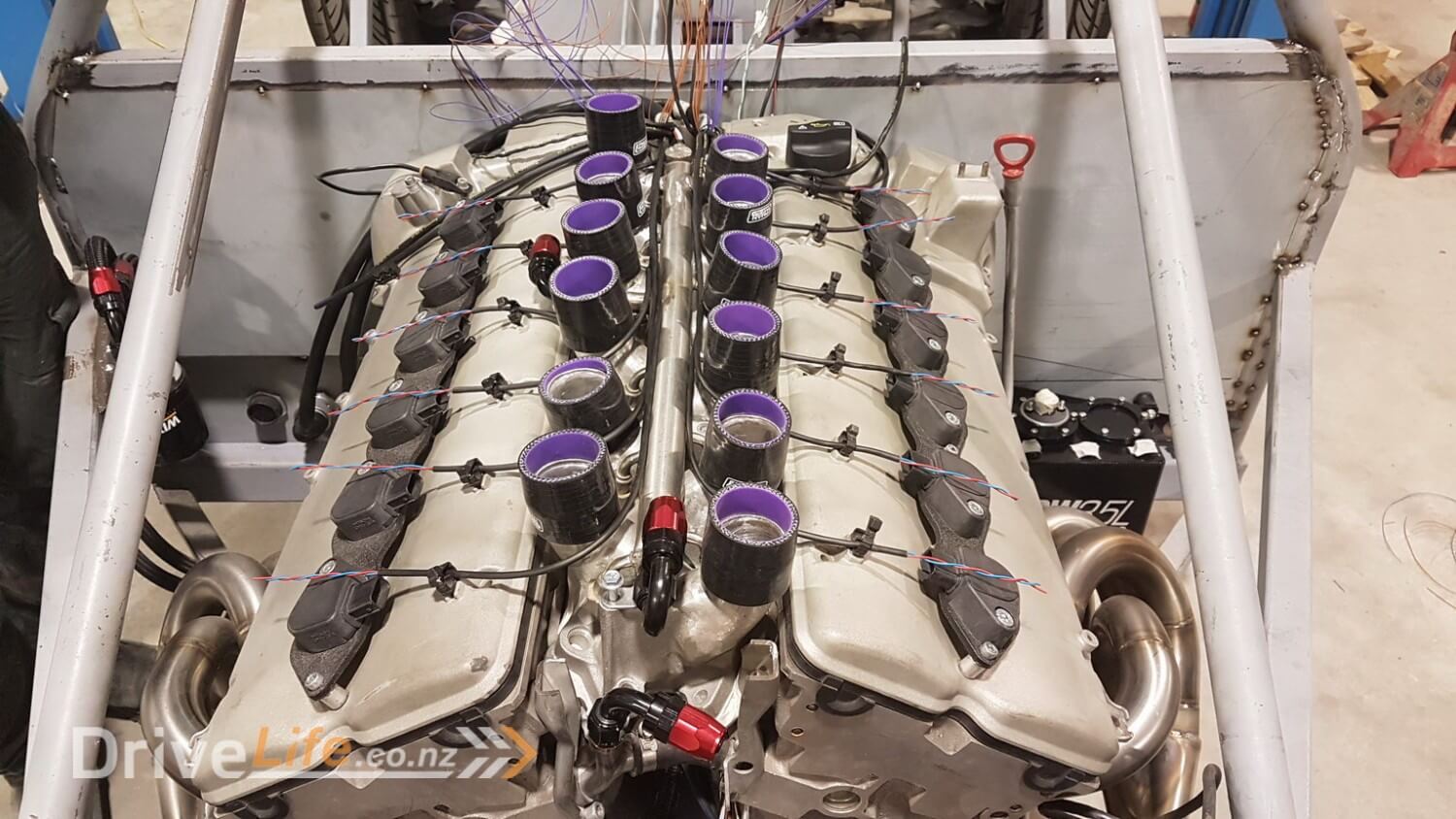
These photos start to give you an idea of just what we’ve got ourselves into with this build ! So many wires and this is just the engine which actually isn’t even half of the wiring required for the whole car.
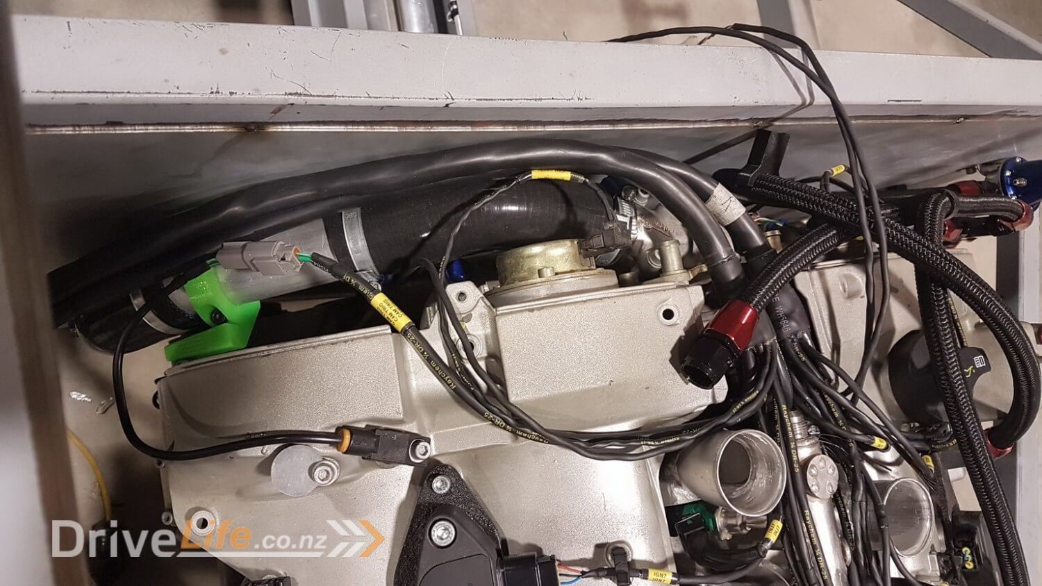

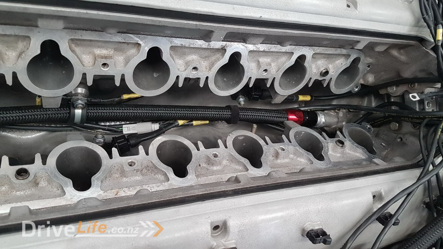
Nestled right down in the ‘V’ of the engine you can see the 2 engine knock sensors, one on each side of the engine and offset front and back also to make sure we get the best picture of what might be going on if anything bad starts to happen.
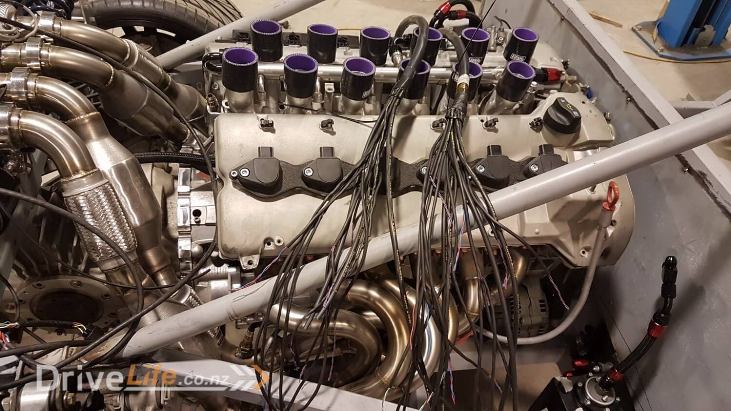
All finished for the engine side of things at least !
Next was to get started on the 3rd and 4th bulkhead looms which are to run things like suspension travel sensors, ride height sensors and controllers, rear lights, airbrake, exhaust muffler system etc
That little paragraph above makes the whole process seem like it’s really quick and easy when in fact each of those bulkhead looms took approx 15-20 hours each to make, that’s just the bulkhead end and the heatstrink for the main part of the loom, there’s still more hours needed to finish the other end, heatshrink, label and terminate with plugs !
Lance and I so far have spent close to 5 months of part time work to get this far.
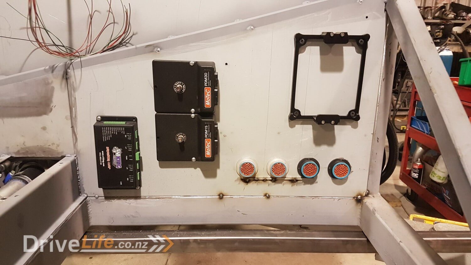
As I mentioned earlier on, the amount of wiring had taken us both back a bit, as although we felt like we’d planned things out pretty well (15 pages on a spreadsheet) and there was 3 of us in total that went over that spreadsheet, we still missed things. Although we were able to get around the extra wiring needed what we couldn’t work around was the need for an extra Motec PDM (power distribution module). I will cover off the functions of the Motec PDM for those who don’t know about them in a seperate episode.
Once we had this unit we could get started wiring from the cabin side of the bulkhead connector to the devices (ECU, PDM, polarity reversers, earthing points and Viking suspension controller).
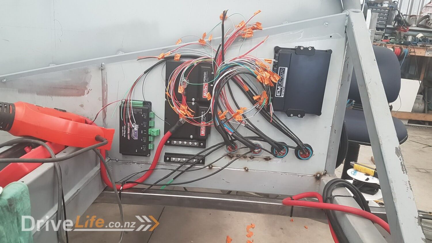
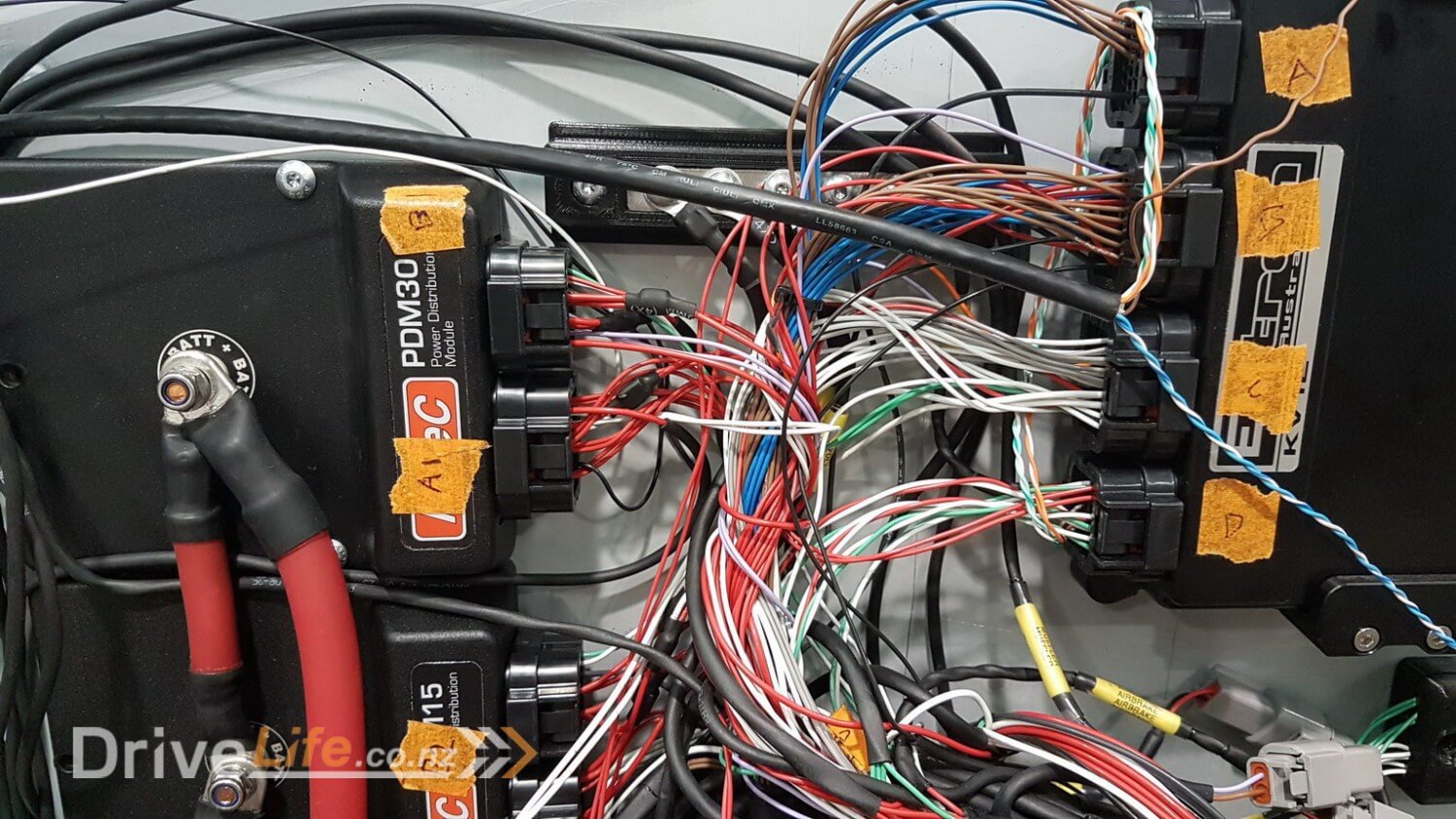

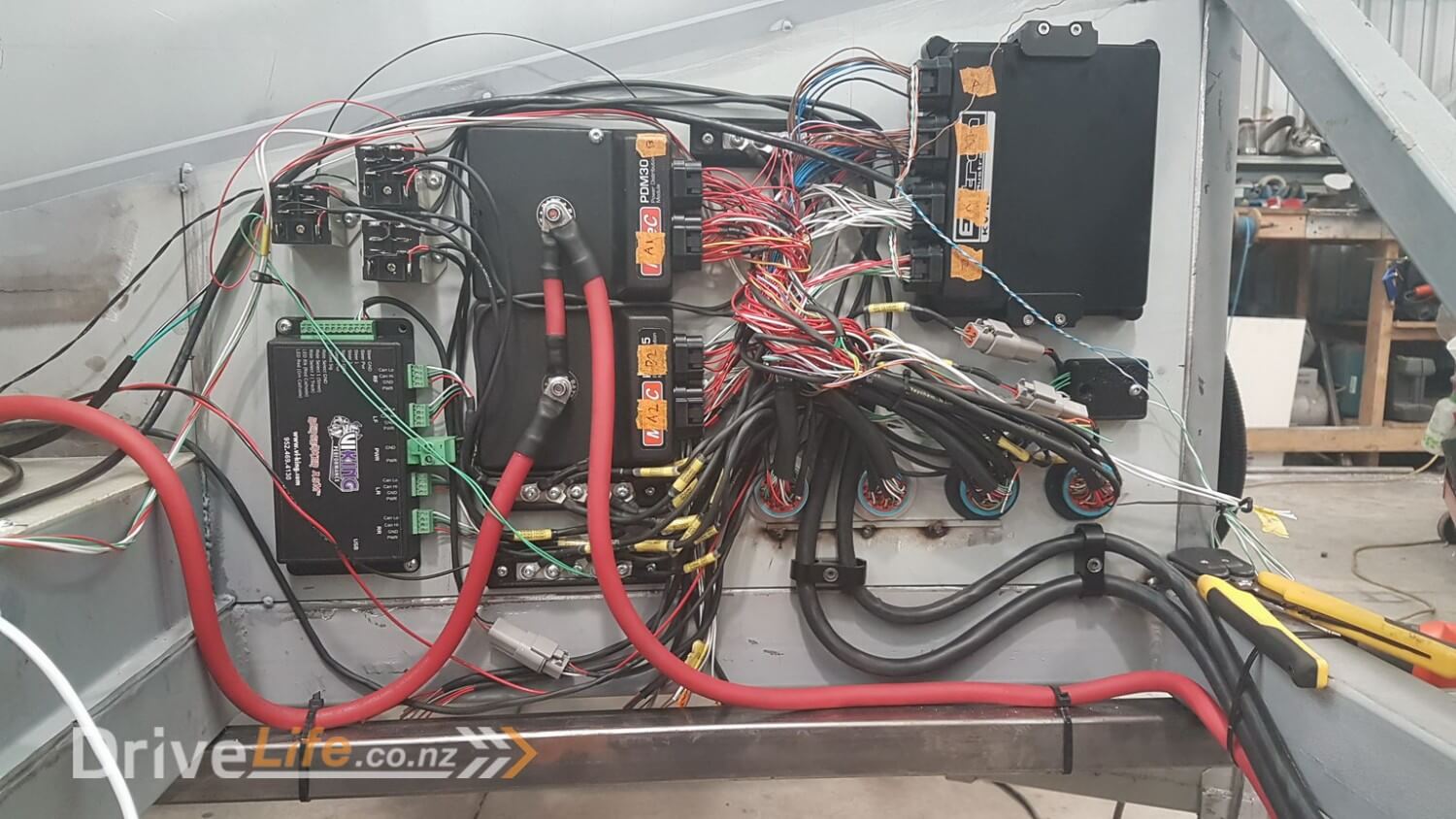
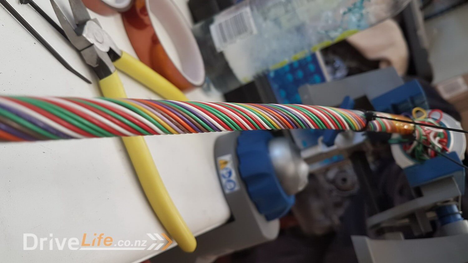
With so much wiring coming to one place, there’s no “pretty” way to make it all work, and although it’s not finished in these photo’s it is pretty close and I think given the amount of connections it’s come out pretty well. There are close to 300 connections and ……wait for it……. 900 metres of wire in the entire loom for front and back. Luckily Lance made sure that I used Tefzel wire which is a very small and light weight wire that can cope with more current than most wire and exceeds the spec we were looking to meet with our loom. Clever guy that Lance !
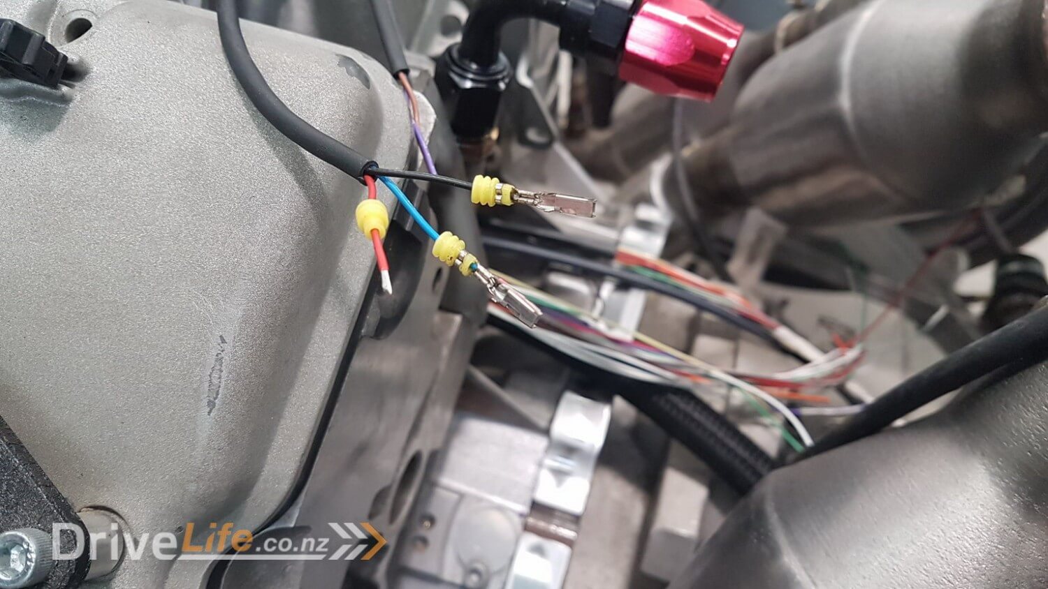
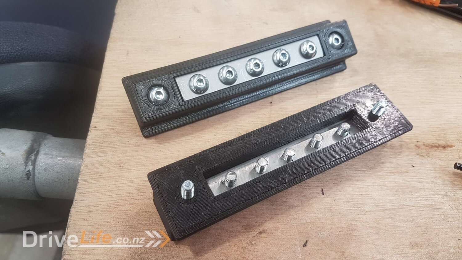
One thing I hadn’t realised as we planned and executed this loom was the amount of ground (earth), sensor ground and +5V connections that we would have. Each analogue sensor (and there’s plenty of them) needs a wire back to the sensor ground and also one to the +5V. To make this as tidy as possible I used my 3D printer to create a bus bar where we could mount everything to in a tidy manner.
We basically connect one end to the +5V connection and then all of the other bolts retain multiple incoming +5V connections. The process was the same with the ground and sensor ground.
You can see how these are used in some of the photo’s above.
So this brings an end to this episode, but the wiring dynasty will continue later as we progress other parts of the car and get closer to starting the engine !
Please feel free to comment or ask questions, I really love sharing and discussing our build and cars in general with other readers.
There’s a newer entry in this story, please click here – FZ12 – Part 30
If you’ve missed the last part of our story then click here FZ12 – Part 28
or if you want to go right to the beginning then click here FZ12 – Part 1


Absolutely loving this build Fraser.! Everything is so well executed, and looks the part.!
I thought doing a wiring loom for a 4age in a ae86 was time consuming.. This is next level haha.
Keep it up, cant wait to see more posts and the final product.!!
Thanks very much Derek. As with everything, we’re having to work within the skills we have, but with Lances help I don’t think we could have done a much better job on the wiring loom ! I am really happy so far. With so many wires and connectors and we didn’t have a single issue with pins or connectors not working etc.
Thanks for following the project, we can’t wait to get it to the point where we can actually drive the thing either, but it’s still a while away, but slowly slowly catchy monkey ! 🙂
900m of wire is something I’d think of a house for, not a car
Hi Kyle, Yeah it blew our minds when we started to add up what we’d bought vs what we had left when it came to wire ! It’s quite easy to see how it builds up though.
For instance there are 3 wires for each coil and 2 wires for each injector. The run from the engine to the ECU is close to 2m, so that’s 10M per cylinder and 12 cylinders so close to 120M just for coils and injectors alone !
Really lucky that Lance who had the experience with this stuff pushed me to use Tefzel wire instead as it’s probably half the weight and size of traditional wire of the same rating.
Thanks for following.
What program are you using to create your wiring diagrams? I’m looking into perhaps doing a similar build with the same engine, is there a more efficient method of contact for you if you wouldn’t mind answering a few questions?
Hey mate, will e-mail you separately, but didn’t use any program for wiring diagrams, we used an Excel spreadsheet ….one page for each connector on the firewall and one page for each plug on the ECU and PDM.
Once we mapped out everything that we wanted from the engine to ECU, PDM to engine, etc etc it pretty much sorts itself out. In the sheet I just overlayed the information from the PDM for which ports were what current level (some are 20amp and some are 8amp) so I knew to map larger things to the larger PDM ports and that was it really.
When you’re using a PDM it’s really easy to do wiring as everything tracks back to a single location. Not like traditional fuse boxes, relays etc. PDM’s cost more than the old school way, but save so much time, wire etc and give you control to do things you could never do with traditional wiring setups so I would never build a custom car or scratch built without one……no brainer.
Hope that’s helpful.
Fraser